Chapter 1. Get Started
Note: ESP32-S2 series of chips only supports ESP-IDF master or version v4.2 and higher.
Hardware Reference
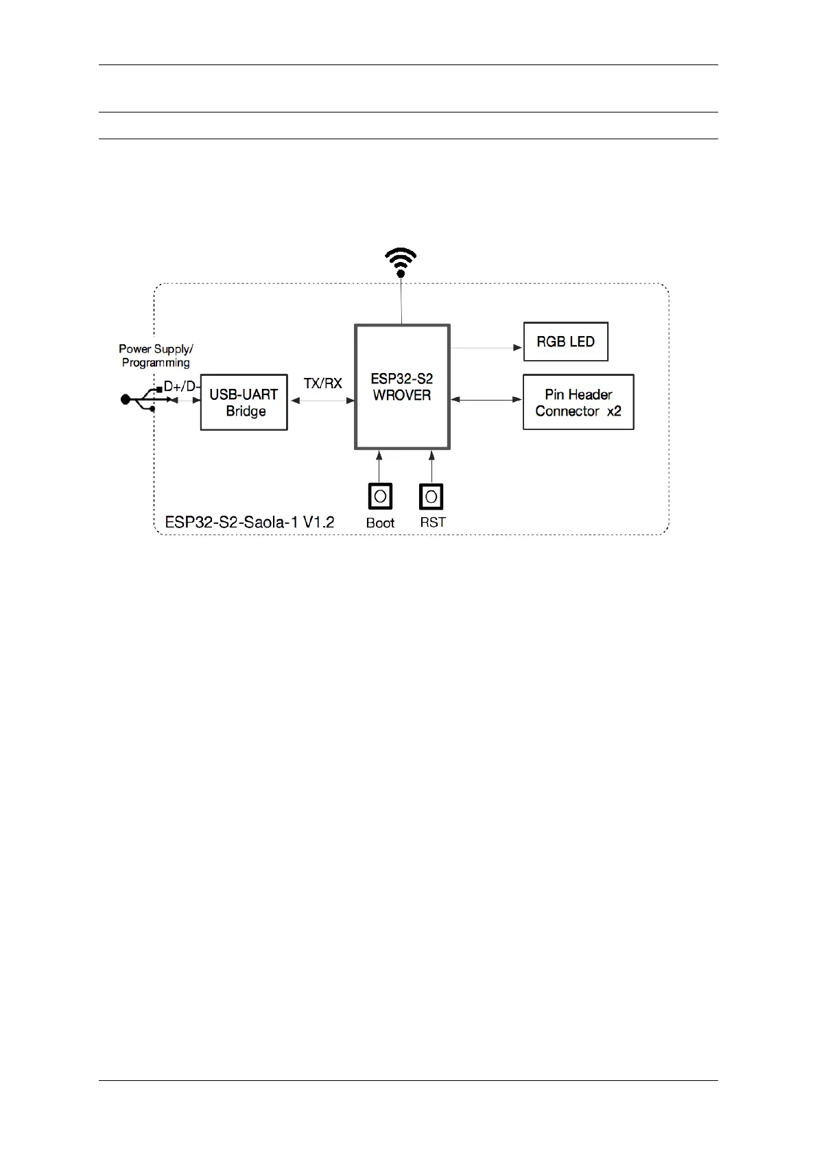
Block Diagram A block diagram below shows the components of ESP32-S2-Saola-1 and their interconnections.
Fig. 4: ESP32-S2-Saola-1 (click to enlarge)
Power Supply Options There are three mutually exclusive ways to provide power to the board:
• Micro-USB port, default power supply
• 5V and GND pin headers
• 3V3 and GND pin headers
It is recommended to use the first option: Micro-USB Port.
Header Block The two tables below provide the Name and Function of the pin headers on both sides of the board
(J2 and J3). The pin header names are shown in ESP32-S2-Saola-1 - front. The numbering is the same as in the
ESP32-S2-Saola-1 Schematics (PDF).
Espressif Systems 7
Submit Document Feedback
Release v4.4