Chapter 1. Get Started
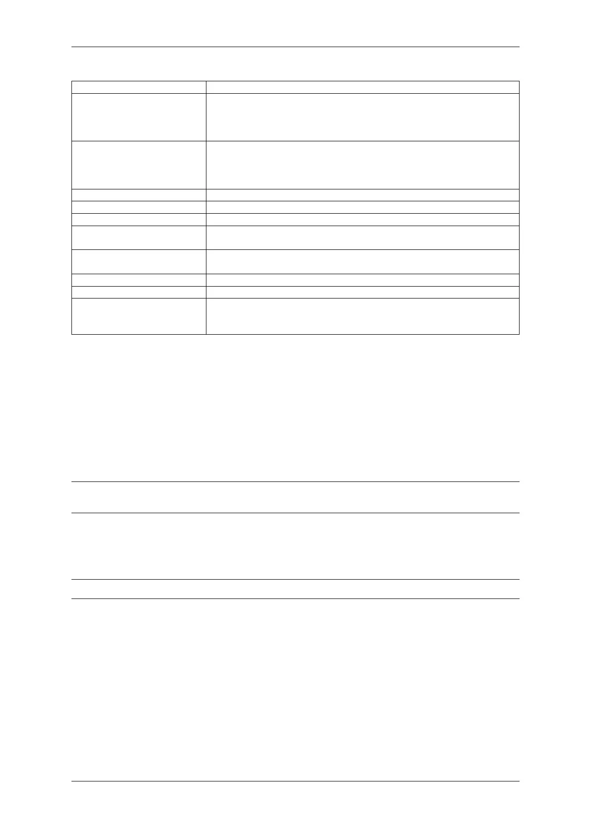
Key Component Description
ESP32-S2-MINI-1 or ESP32-
S2-MINI-1U
ESP32-S2-MINI-1 and ESP32-S2-MINI-1U are two powerful, generic Wi-Fi
MCU modules that integrate ESP32-S2FH4 chip. ESP32-S2-MINI-1 comes
with a PCB antenna, and ESP32-S2-MINI-1U with an external antenna con-
nector. They both feature a 4 MB external SPI flash.
Pin Headers All available GPIO pins (except for the SPI bus for flash) are broken out to the
pin headers on the board. Users can program ESP32-S2FH4 chip to enable
multiple functions such as SPI, I2S, UART, I2C, touch sensors, PWM etc. For
details, please see Header Block.
3.3 V Power On LED Turns on when the USB power is connected to the board.
USB to UART Bridge Single USB-UART bridge chip provides transfer rates up to 3 Mbps.
Reset Button Reset button.
Micro-USB Port USB interface. Power supply for the board as well as the communication in-
terface between a computer and the ESP32-S2FH4 chip.
Boot Button Download button. Holding down Boot and then pressing Reset initiates
Firmware Download mode for downloading firmware through the serial port.
RGB LED Addressable RGB LED, driven by GPIO18.
5 V to 3.3 V LDO Power regulator that converts a 5 V supply into a 3.3 V output.
External Antenna Connector On ESP32-S2-MINI-1U module only. For connector dimensions, please refer
to Section External Antenna Connector Dimensions in ESP32-S2-MINI-1 &
ESP32-S2-MINI-1U Datasheet.
Start Application Development Before powering up your ESP32-S2-DevKitM-1(U), please make sure that it is
in good condition with no obvious signs of damage.
Required Hardware
• ESP32-S2-DevKitM-1(U)
– For ESP32-S2-DevKitM-1U, an antenna is also required.
• USB 2.0 cable (Standard-A to Micro-B)
• Computer running Windows, Linux, or macOS
Note: Be sure to use an appropriate USB cable. Some cables are for charging only and do not provide the needed
data lines nor work for programming the boards.
Software Setup Please proceed to Get Started, where Section Installation Step by Step will quickly help you set up
the development environment and then flash an application example into your ESP32-S2-DevKitM-1(U).
Note: ESP32-S2 series of chips only is only supported in ESP-IDF master or version v4.2 and higher.
Hardware Reference
Block Diagram A block diagram below shows the components of ESP32-S2-DevKitM-1 and their interconnec-
tions.
Power Supply Options There are three mutually exclusive ways to provide power to the board:
• Micro-USB Port, default power supply
• 5V and GND pin headers
• 3V3 and GND pin headers
It is recommended to use the first option: Micro-USB Port.
Espressif Systems 12
Submit Document Feedback
Release v4.4