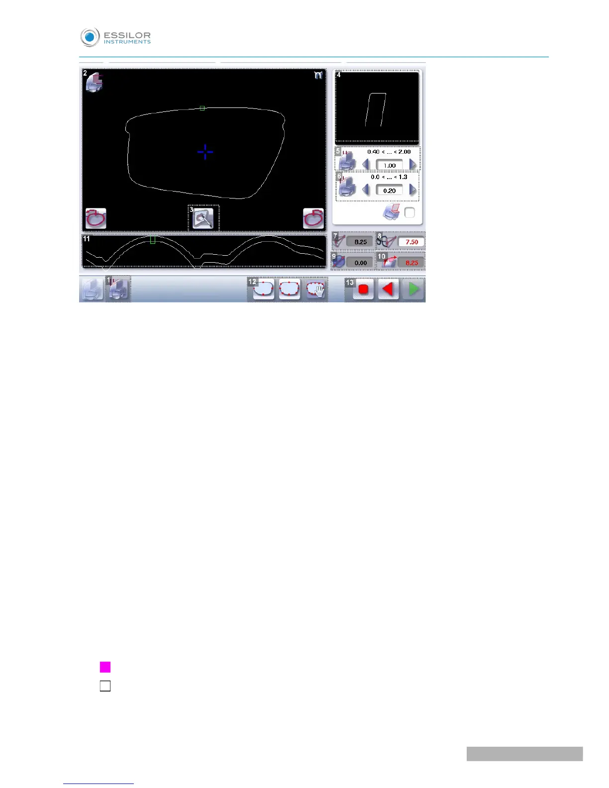
1. Front surface tracking step bevel screen
2. Work area
Image of the shape to be edged
3. Access to step bevel definition screen
4. Zoom window
Represents the bevel profile at the position of the cursor.
5. Width of the flat side of the bevel
The value of the flat side of the bevel must be between 0.4 mm and 2 mm.
6. Front surface tracking value
The value of front surface tracking must be between 0 mm and 1.3 mm. This value is definable only in
the “front surface tracking” screen.
7. Lens base
8. Frame base
9. Reminder of size reduction/increase applied to lens diameter
10. Bevel Base_Range of values of the lens base necessary for the frame
If the lens base used is out of range: the range values are shown in red.
11. Window showing the bevel trajectory on the lens section
Centre of the flat side of the bevel
Front surface/rear surface of lens
12. Number of shelf bevel values