ES415.1 - User’s Guide30
ETAS
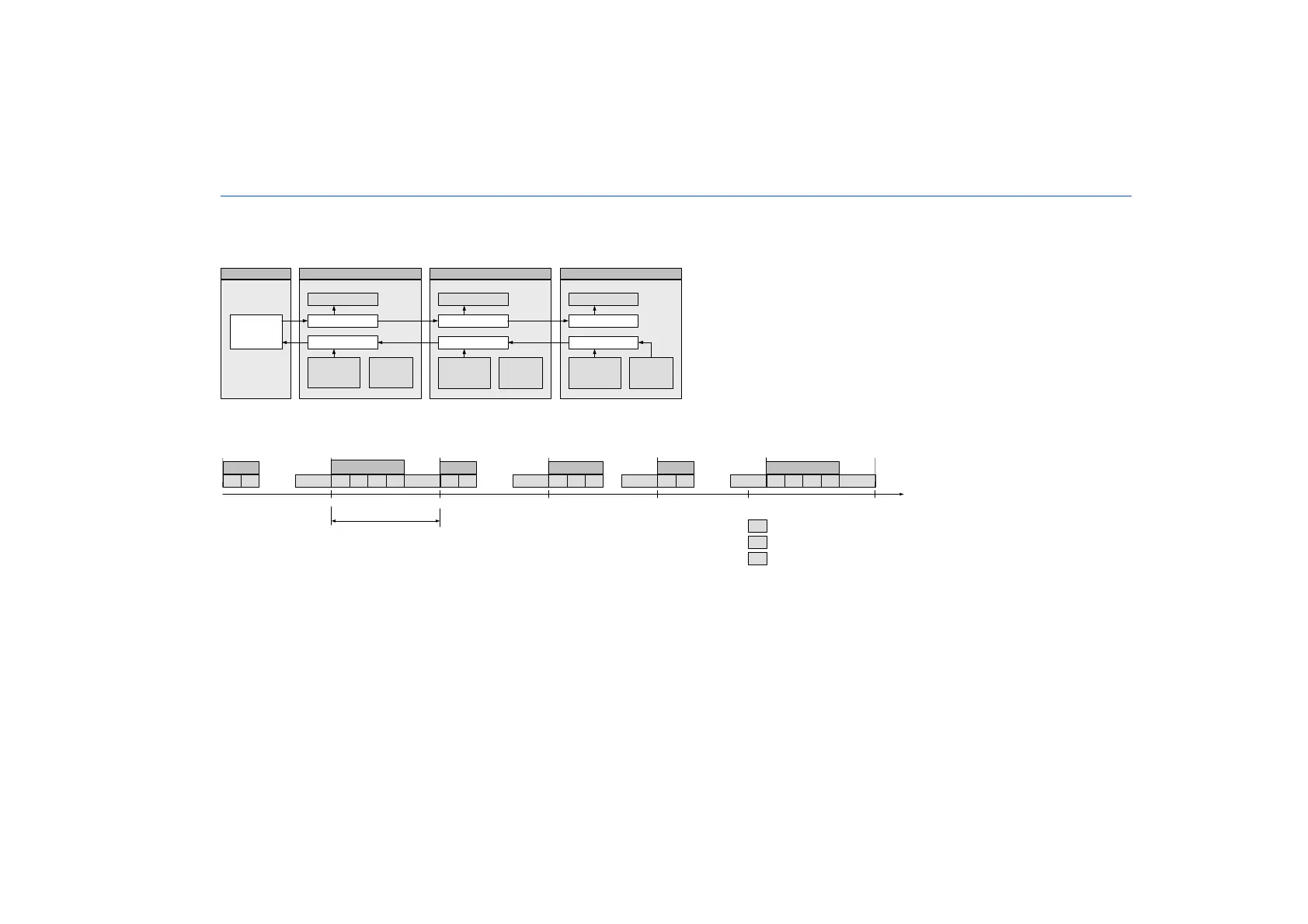
Example 2
Fig. 4-10 on page 30 shows an example in which three modules with different acquisition rates are linked to each other. The transfer
scheme for this configuration is shown in Fig. 4-11 on page 30.
Fig. 4-10 Time-Multiplex Data Transfer Between an ES400 Module Chain and a PC
Fig. 4-11 Transfer Scheme for Example 2 (Simplified, Not True to Scale)
In this example, the third module periodically generates 2
16
(65536) time slices (Ethernet frames) each 100 microseconds long. The ES400
modules 1, 2 and 3 acquire measurements at a rate of 10 kHz, 2 kHz and 5 kHz. Module 1 links its measurements to each Ethernet frame,
module 2 to every fifth Ethernet frame and module 3 to every second Ethernet frame (bottom figure).
Independently of this, control variables can be transferred at the same time from the PC to the modules.
Control variables
Measured
values M1
Rate: 10 kHz
Signal injection
Signal ext raction
Fr am e
Generat o r
(inakt iv)
MODULE 1
Control variables
Measured
values M 2
Rat e: 2 k Hz
Signal injection
Fr am e
Generat o r
(inakt iv)
MODULE 2
Signal ext raction
Control variables
Measured
values M 3
Rat e : 5 k H z
Signal injection
Signal ext raction
Fr am e
Gen erat or
(10 kHz)
MODULE 3
Et h e r n et
100 Mbit /s
PC
Et hernet Frame 1
M1H R M1H RM3 M2 M1
H
R
t [µs]
2000 100
Frame 2Fr. 65536
Periode Frame Generator
M3 M1H R
Frame 3
M1H R
Frame 4
M3 M2 M1H R
Et hernet Frame 5
300
500
400
H UDP/IP Header
R
Reserved for additional
communication
Mn Measured values of module n

 Loading...


