04-2017 5325 00 69
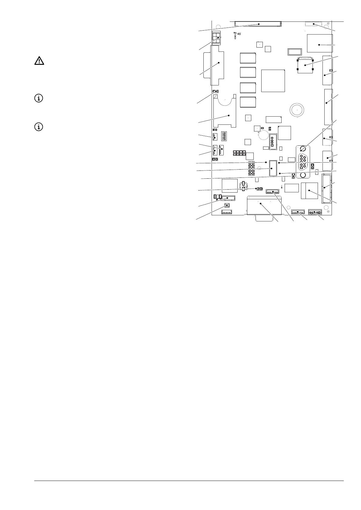
CPU BOARD
The CPU board manages the communica-
tion with the touchscreen, payment sys-
Be careful to not damage the touch-
screen connections and antenna when
removing the CPU board (e.g. when
The touchscreen is connected to the
of the CPU board.
the CPU board.
1
2
3
4
5
6
10
7
11
12
13
14
16
15
17
18
19
20
21
22
25
24
23
26
27
2930
28
8
9
Fig. 49
1. (J2) connectivity switch connection
2. Modem connection
3. (JP2)
CAN Bus jumper 1 closed
4. (JP5)
CAN Bus jumper 2 closed
5. usB connector
6. Yellow
reset LED
7. (J45) Cup sensor
8. (J48) Not used
9. (J34) Not used
10. SIM card slot*
11. (JP4)
sIM CArd*jumper present
12. (J16) Not used
13. (CN31) Not used
14. (CN55) Not used
15. Wi-Fi antenna**
16. Ethernet connector (1 Gbit/s)*
17.
MICro sd* slot
18. (J42) stroke counter, lighting, wash button and
programming button.
19. (J43) digital inputs/outputs
20. rs232 serial connector
21. (J41) Not used
22. (J35) Payment systems
23. Red
BoArd power supply LED
24. Yellow
ruN LED
25. (J36) Validator
26. Ethernet connector (100 Mbit/s)*
27. (CN9) not used
28. (J47) not used
29. (CN34) not used
30. (CN29) power supply and
CAN Bus
* If present
**. On the back of the board