Glossary
604 FTB-700G/800 Series
CPRI
CPRI Model
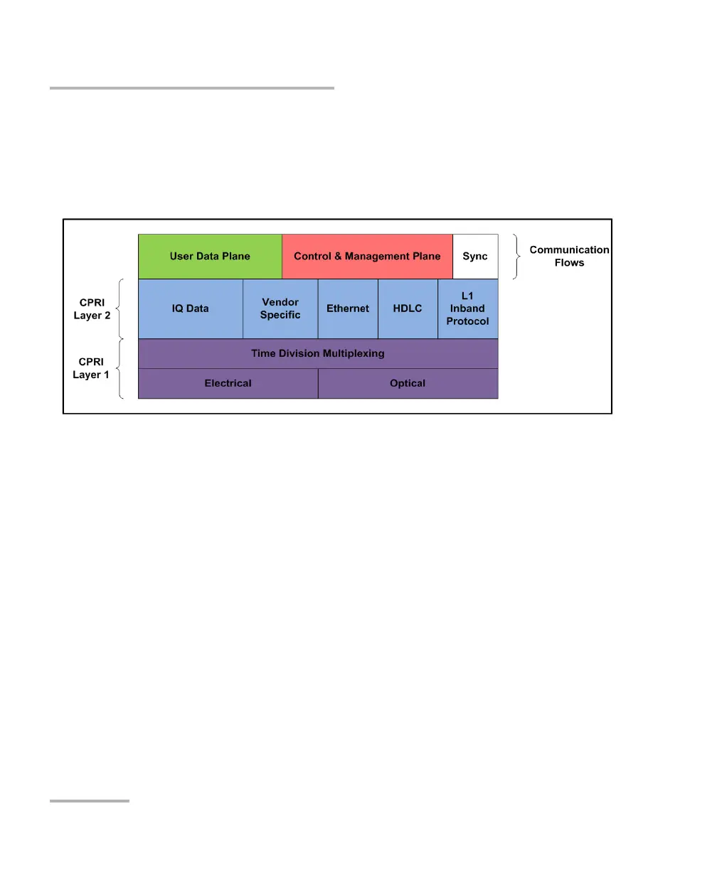
The CPRI Model revolves around the 3 communication flows described
above. CPRI defines only the Layer 1 and Layer 2 associated to these
communication flows as outlined in the following figure.
The User Data Plane contains mostly voice/data traffic in the form of IQ
Data samples. IQ Data digitally encodes the change in amplitude/phase of
a user device modulated signal sampled at the RE antenna.
The Control & Management Plane maintains the CPRI link itself and
provides the facility to manage the operation of the RE radio functions. It is
done through the L1 Inband Protocol which provides a bit oriented channel
defined to support link specific alarms (R-LOS, R-LOF, …). Also, the
Ethernet/HDLC channel offer two OAM&P channel alternatives which are
respectively high and low bandwidth with rates configurable based on the
CPRI line interface rate. These carry proprietary information between the
REC and RE. Some Vendor Specific overhead is also available.
Finally, the Synchronization flow ensures frequency stability and offers the
overhead necessary for frame alignment between the REC and RE to
ensure hitless channel or frequency hopping. All these flows are time
division multiplexed onto one optical fiber for CPRI field deployments such
as Distributed Antenna Systems (DAS).