1 = Captive screws 4 = AC power input connector
2 = Status LEDs 5 = Handle
3 = Fans
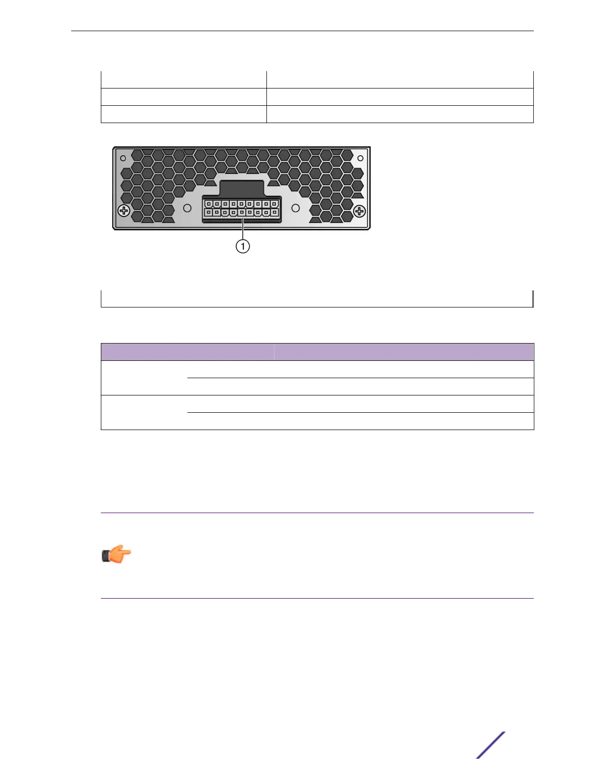
Figure 101: STK-RPS-1005PS Rear Panel
1 = 18-pin Redundant Power Supply connector
Table 37: STK-RPS-1005PS LED Status Definitions
LED LED Color Status
AC OK Green AC input within operational range
O No AC voltage or AC voltage is outside the operational range
DC OK Green Power supply successfully providing 55 VDC to the system
O Power supply malfunctioning
For technical specifications, including pin locations and functions, see STK-RPS-1005PS Redundant
Power Supply Technical Specifications on page 389.
VX-RPS-1000 Redundant Power Supply
Notice
Extreme Redundant Power Supplies (RPS) do not support the ability for the RPS to be
connected to an operational switch. Connecting an RPS to an operational switch can have an
adverse eect on the switch. It is best practice that both the switch and the RPS be powered
down prior to cabling them together. Once the cabling is completed, turn on the RPS, then
turn on the switch.
The VX-RPS-1000 provides load sharing, backup, or additive power for the V400 Virtual Port Extender.
Power Supplies for Use with Your Switch
ExtremeSwitching and Summit Switches: Hardware Installation Guide 103
 Loading...


