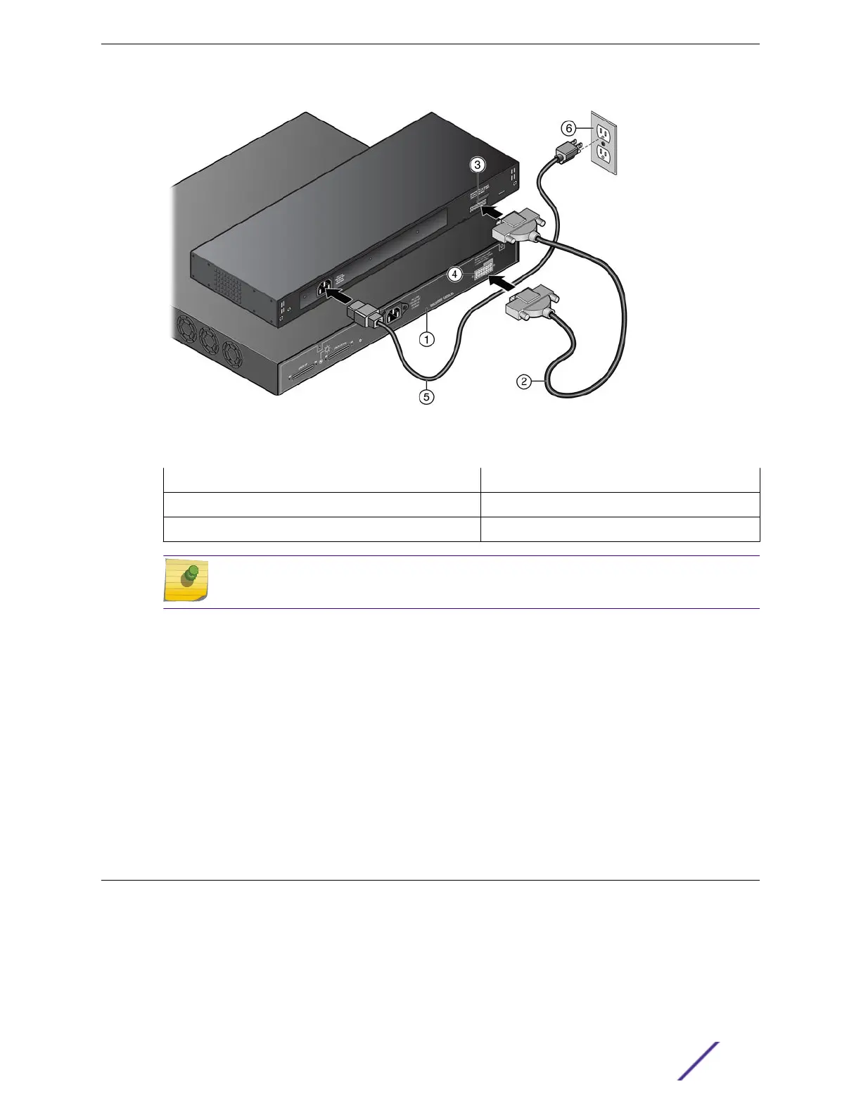
Figure 187: RPS Cable and AC Power Cord Connections for the RPS-500p
1 = PoE-compliant switch 4 = Redundant Power Supply connector on switch
2 = RPS cable 5 = AC power cord
3 = Redundant Power Supply connector on power supply 6 = AC power outlet with ground connection
Note
AC power cords and outlets vary depending on country.
3 Connect the AC power cord to the AC input power connector on the power supply.
4 Plug the AC power cord into the main AC power outlet.
The AC OK and DC OK LEDs on the front of the power supply turn green to indicate that the connection
was successful and the power supply is operating properly.
If the LEDs do not light properly, follow these steps to troubleshoot:
•
Check the AC power cord connection at the AC power source and make sure the power source is
within specification.
•
Check the AC power connection to the power supply.
•
Swap the AC power cord with one that is known to work properly.
Installing an STK-RPS-150PS Redundant Power Supply
You can install an STK-RPS-150PS as a standalone unit or in one of the following RPS shelves:
•
STK-RPS-150CH2, a two-slot shelf
•
STK-RPS-150CH8, an eight-slot shelf
If you are installing the STK-RPS-150PS as a standalone unit, see Connecting the RPS Cable and AC
Power Cord on page 246.
Installing External Power Supplies
ExtremeSwitching and Summit Switches: Hardware Installation Guide 241
 Loading...


