EasyManuals Logo

Extreme Networks ExtremeSwitching X440-G2 Series User Manual

Extreme Networks ExtremeSwitching X440-G2 Series
413 pages
To Next Page IconTo Next Page
To Previous Page IconTo Previous Page
Page #201 background imageLoading...
Page #201 background image
b Slide the spade terminal of the positive wire (–48 V RTN) under the captive square washer on the
positive terminal (labeled +).
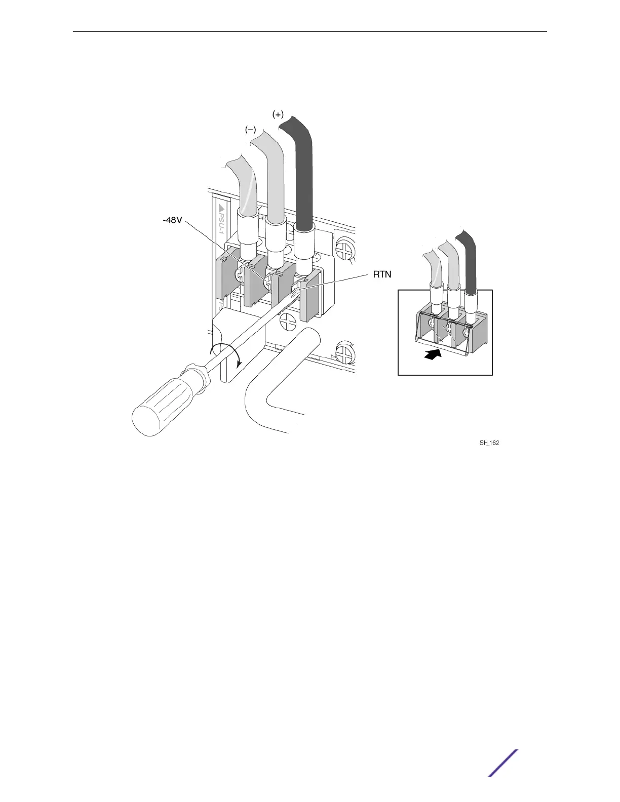
Figure 153: Connecting the Positive Power Wire to a –48V Source (550 W DC
Power Source)
6 Tighten both screws on the terminal block to 7 inlb (0.79 N m).
7 Snap the cover into place over the terminal block.
8 Connect the cables to the DC source voltage, using hardware appropriate to the installation site and
following local and national electrical codes.
9 Energize the DC circuit.
Leave the ESD strap permanently connected to the rack, so that the strap is always available when you
need to handle ESD-sensitive components.
You can now connect network interface cables to the switch, using the instructions in Connecting
Network Interface Cables on page 220.
Installing Your Extreme Networks Switch
ExtremeSwitching and Summit Switches: Hardware Installation Guide 201

Table of Contents

Questions and Answers:

Question and Answer IconNeed help?

Do you have a question about the Extreme Networks ExtremeSwitching X440-G2 Series and is the answer not in the manual?

Extreme Networks ExtremeSwitching X440-G2 Series Specifications

General IconGeneral
Form FactorRack-mountable
VLAN SupportYes
Humidity5% to 95% non-condensing
ModelX440-G2 Series
Port TypeGigabit Ethernet
Switching Capacity176 Gbps
Forwarding Rate131 Mpps
StackingYes, up to 8 switches
Layer SupportLayer 2/3
Operating Temperature0°C to 50°C
Product TypeSwitch
Jumbo Frames9216 bytes
AC Power Supply100-240 VAC, 50-60 Hz
Storage Temperature-40°C to 70°C
Port Configuration24 or 48 ports
Power over Ethernet (PoE)Optional

Related product manuals