2-3MLC 226 Series • Installation: Labeling, Cabling, Mounting
PRELIMINARY
Panels and Cabling
Host-MLC RS-232 cabling
PROJECTOR
MLC 226 IP
1
2
3
4
5
6
VOLUME
CONFIG
IR
ON
OFF
LIGHT
ON
LIGHT
OFF
LAPTOP
VCR
DVD
PC
AUX
VIDEO
LECTERN
PC
AUTO
IMAGE
HOST
CONTROL
R
1=D INPUT 2=Tx 3=Rx
5=GND, 38400, N, 8, 1
PRESS TAB WITH
TWEEKER TO REMOVE
LAN
21
MLC 226 IP Front Panel
MLC 226 IP Rear Panel
1
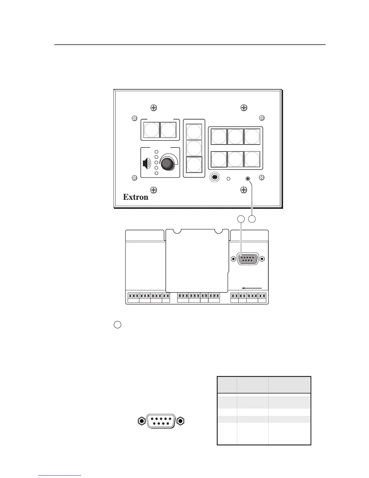
Rear panel Host Control port — For MLC configuration and control, connect
a Windows
®
-based PC or an RS-232 control system to the MLC via this
female, 9-pin HD connector. This connector also has one pin designated for
digital input/output.
RS-232 protocol:
• 38400 baud
• 1 stop bit
• no parity
• 8 data bits
• no flow control
The pin assignments of this
connector are as follows:
DB9 Pin Locations
Female
51
96
RS-232
Pin Function Description
1 – Digital I/O
2 Tx Transmit data
3 Rx Receive data
4 – No connection
5 Gnd Signal ground
6, 7 – No connection
8, 9 – No connection