2-5MLC 226 Series • Installation: Labeling, Cabling, Mounting
PRELIMINARY
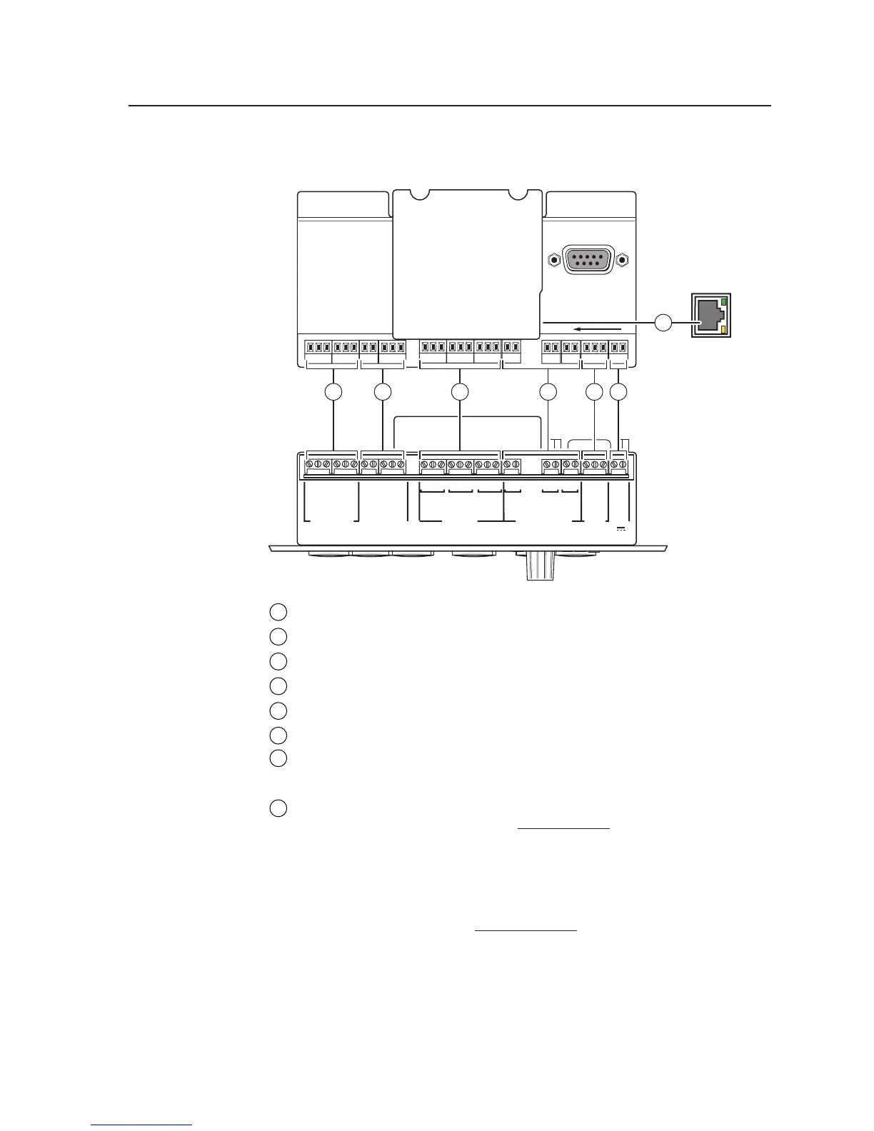
Bottom/rear panel and cabling
HOST
CONTROL
R
1=D INPUT 2=Tx 3=Rx
5=GND, 38400, N, 8, 1
PRESS TAB WITH
TWEEKER TO REMOVE
PROJECTOR
RS-232/IR RS-232 12V
CM/ IR SCP
A B C D E
C 1 2
A
RELAYS
IR/SERIAL OUT
MLS PWR
C 3 4
B
C 5 6
C
S G
A
S G
BAB
S G
C
Tx/IR
Rx
GROUND
PWR SNS
GROUND
+12V OUT
Rx
Tx
GROUND
GROUND
+12V IN
+12V OUT
GROUND
CONT MOD
IR IN
SCP COM
LAN
MLC 226 IP Rear Panel
MLC 226 IP Bottom Panel
LAN (IP)
Connector
Side View
5 6
7
41 2 3
1
Projector control (Projector RS-232/IR) and display power sensor port
2
CM/IR/SCP port
3
Relay ports (24 V, 1 A)
4
IR/Serial Output ports
5
MLS connector
6
PWR (power) connector
7
LAN (IP) connector and LEDs
Projector/display connections
1
Projector control (Projector RS-232/IR) port (-5 VDC to +5 VDC) — Connect a
cable between the projector and the
left three poles of this 3.5 mm direct
insertion captive screw connector for RS-232 one- or two-way projector/
display control. Alternatively, the Tx/IR and Ground pins can be used for
one-way infrared signal output. From this port, commands from a projector
driver or user-defined command strings entered via the Windows-based
configuration program can be sent to the display device.
Connect a cable between the
right three poles of the Proj Cont port and
accessories such as an Extron Power Sensor. The Power Sensor can be used to
let the switcher know when the projector is on or off. If these pins are not
connected to a Power Sensor, the SNS and ground pins can be used for digital
input as can pin 1 and ground of the 9-pin D RS-232 Host Control port.
Digital input: pin 1 and the ground pin together act as a digital input port
(depending on configuration). This allows for an additional way to trigger
events or functions (such as triggering relays, issuing commands, or sending
an e-mail).