Installation: Labeling, Cabling, Mounting, cont’d
MLC 226 Series • Installation: Labeling, Cabling, Mounting2-14
PRELIMINARY
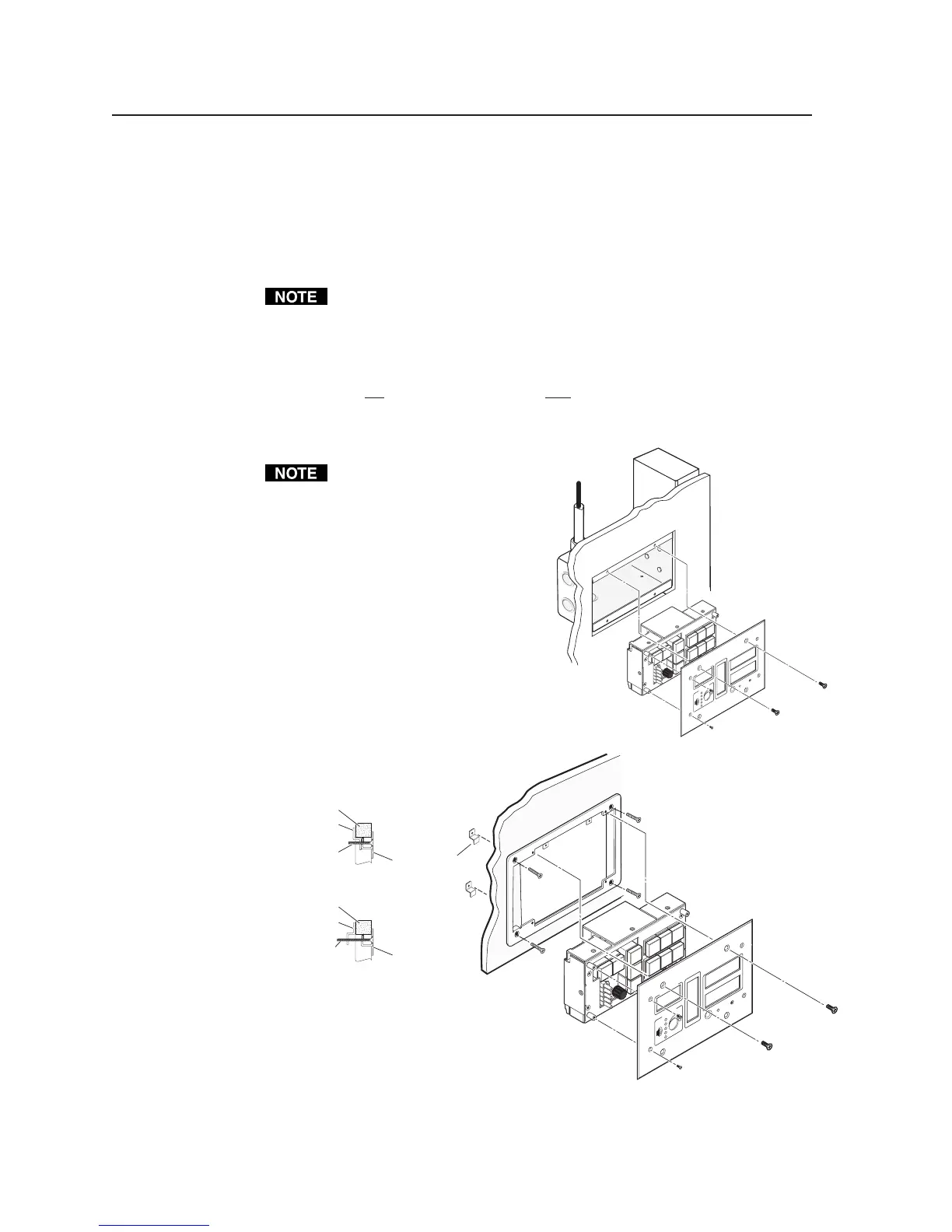
Mounting the MLC to an electrical box or mud ring
1. With power disconnected at the source, insert the MLC into the wall or
furniture.
2. Mount the MLC to the wall box or mud ring mounting bracket with the
provided machine screws (mounting screws, as shown in the following
illustrations).
If the MLC (and any accessories such as control modules or an IR Link) is not
mounted to a grounded metal wall box,
• Ground each faceplate directly to an earth ground. Or...
• Tie each faceplate to its circuit board and power supply via a ground pin on
one of the connectors.
Do
not tie a product’s faceplate to both a separate earth ground and the circuit
ground (via a connector pin). If you tie a product to two different ground
sources, you may introduce ground loops or other grounding-related problems
into the system.
For the installation to meet UL
requirements and to comply
with National Electrical Code
(NEC), the MLC must be
installed in a UL approved
junction box. The end user or
installer must furnish the
junction box; it is not included
with the MLC.
3-gang Wall Box
O
F
F
ON
LA
PT
OP
P
C
V
C
R
D
V
D
A
U
X
V
ID
E
O
M
U
T
E
A
U
T
O
IM
A
G
E
E
x
t
r
o
n
P
R
O
J
E
C
T
O
R
1
2
3
4
5
6
V
O
L
U
M
E
C
O
N
F
I
G
I
R
Extron
MLC 226
Detail A
0.75" #6-32 Screw
Backing Clip
Backing Clip
Sheet Rock
Sheet Rock
Mounting Bracket
Mounting Bracket
Detail B
1.25" #6-32 Screw
Backing Clip can
be in either orientation.
See Detail A or Detail B.
OFF
ON
L
APTOP
PC
VCR
DVD
A
UX
VI
DEO
MUTE
AUTO
IM
A
GE
Ext
ron
PROJECTOR
1
2
3
4
5
6
VOL
UME
C
O
N
F
IG
IR
Extron
MLC 226
Mounting the MLC to an electrical box or mud ring