Front Panel Features and Basic Operation, cont’d
MLC 226 Series • Front Panel Features and Basic Operation3-4
PRELIMINARY
When these input selection buttons are configured for input
switching, there is a default 0.5 second delay between when one
input is selected and when a different input can be selected. This
allows time for the projector to adjust to the change of sync signals.
The delay period is adjustable.
If the MLC is used without an optional switcher and the MLC has been
set up for use with a projector, the selectable inputs on the MLC
correspond to the number of inputs available on the projector. If an
optional Extron switcher is connected to the MLC, all six input selection
buttons will be selectable. Which buttons are and aren’t part of the
switching rotation can be determined/set by the projector driver or via
the Windows-based configuration program.
When an input selection button is part of the switching rotation,
pushing that button causes the MLC to send out an SIS input
change command via the MLSRS-232
connector
in addition to sending projector
control commands out the Projector
RS-232/IR port, triggering a relay, or
sending an IR or serial command via an
IR/Serial Out port.
The standard Extron SIS commands sent
via the MLS connector are fixed and cannot be altered. The
command for each input is shown at right.
Volume control
4
Volume knob and LEDs — Rotate this knob to adjust the audio volume.
Volume can be adjusted via this front panel knob or via RS-232/Telnet/Web
browser control. The included configuration software lets you select whether
this knob will control the projector’s audio levels or the optional switcher’s
audio levels. If the knob controls the projector’s audio levels, you can specify
incremental adjustments or range-based adjustments (via device driver only).
See chapter 4 and the MLC 226/104 Configuration Software Help file for
details.
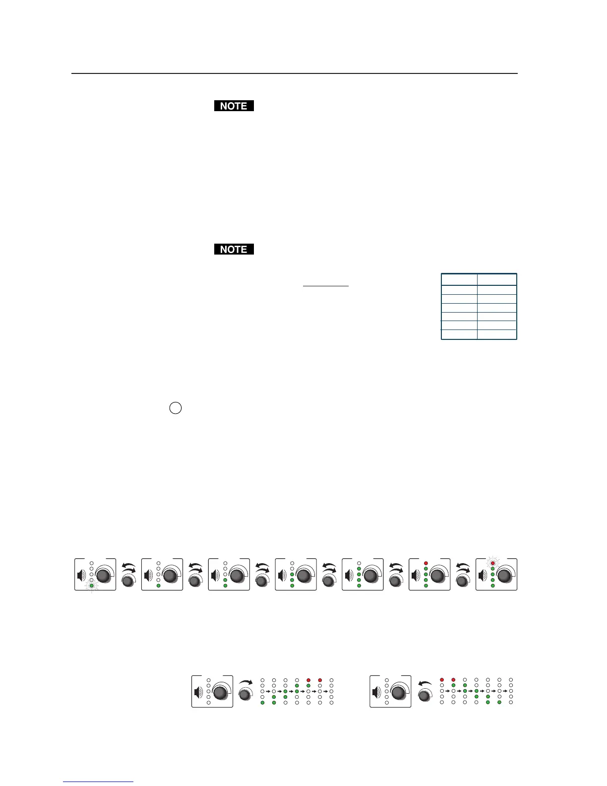
If the MLC is configured for use with a MediaLink Switcher or for some
projectors, the MLC’s LEDs light to indicate volume ranges (with steadily lit
LEDs) and minimum/maximum volume limits (with flashing LEDs), as
shown in the following diagram.
VOLUME VOLUME VOLUME VOLUMEVOLUMEVOLUMEVOLUME
Range-based Volume Adjustment
Minimum,
0% of Max.
Volume
1% to 19%
of Max.
Volume
20% to 39%
of Max.
Volume
40% to 59%
of Max.
Volume
60% to 79%
of Max.
Volume
80% to 99%
of Max.
Volume
100% of
Max.
Volume
If the MLC is configured for increment/decrement volume adjustment, the
LEDs scroll up/down briefly. See the example below.
VOLUME
VOLUME
Increment/Decrement-based Volume Adjustment
Button Command
Input 1 1!
Input 2 2!
Input 3 3!
Input 4 4!
Input 5 5!
Input 6 6!