2-13MLC 226 Series • Installation: Labeling, Cabling, Mounting
PRELIMINARY
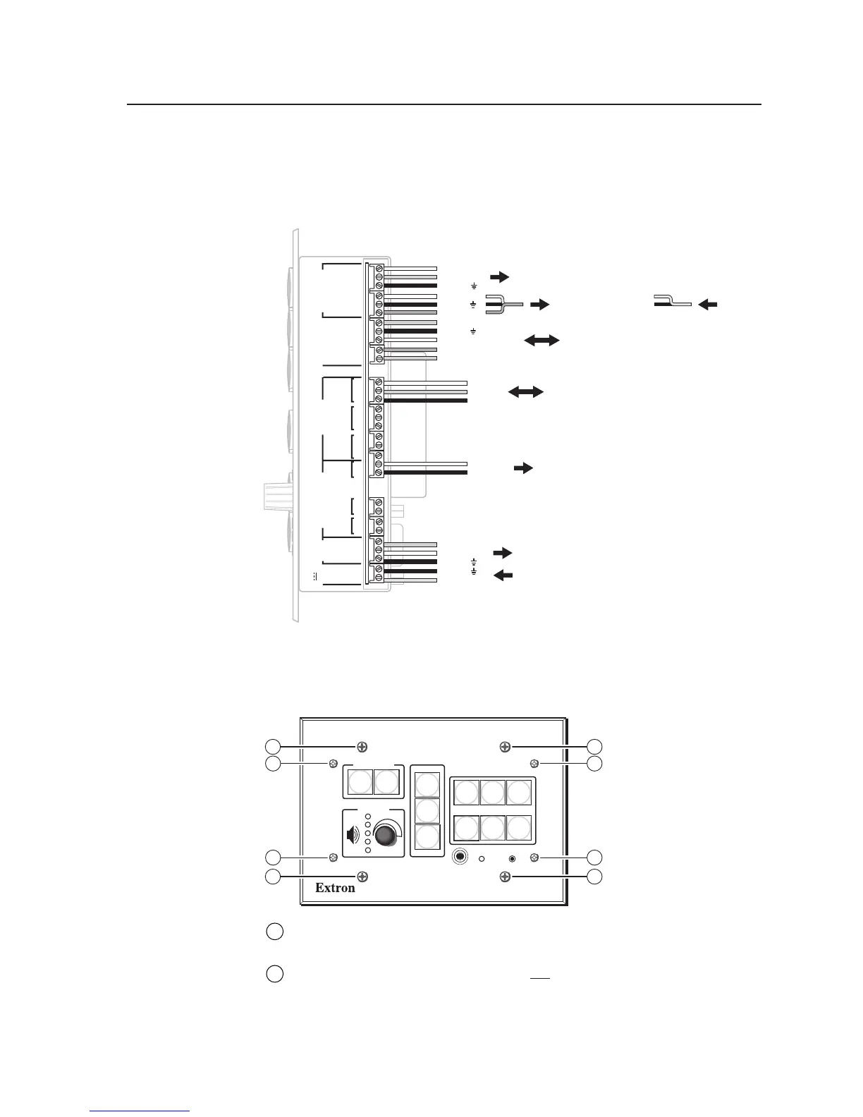
Pinout guide
The illustration below summarizes the pin assignments of all of the MLC’s bottom
panel connectors that are covered in detail on pages 2-5 to 2-12.
PROJECTOR
RS-232/IR RS-232 12V
CM/ IR SCP
A B C D E
C 1 2
A
RELAYS
IR/SERIAL OUT
MLS PWR
C 3 4
B
C 5 6
C
S G
A
S G
BAB
S G
C
Tx/IR
Rx
GROUND
PWR SNS
GROUND
+12V OUT
Rx
Tx
GROUND
GROUND
+12V IN
+12V OUT
GROUND
CONT MOD
IR IN
SCP COM
MLC 226
Bottom Panel
Common
Relay 1
Relay 2
To / from control equipment
(screen control motors, lights, etc.)
To / from optional Extron control modules,
IR Link IR repeater, or SCP control pads
Ground ( )
Transmit (Tx)
Receive (Rx)
To an optional Extron switcher
From an external 12 VDC, 1 A (max.) power supply
Ground ( )
Receive (Rx)
Transmit (Tx)
To a projector or display
To an Extron
Power Sensor
OR
+12 VDC
Ground ( )
Power sense
To an IR Emitter, IR Broadcaster,
or IR or serial (RS-232) controllable device
Ground ( )
+12 VDC input
SCP communication (IR)
Modulated IR (for IR Link)
Ground ( )
IRCM, ACM, RCM
+12 VDC
Digital
input
Ground
Signal (IR)
Mounting the MLC
Once the system has been cabled, configured (see chapter four), and tested, the
controller can be installed in the wall, furniture, equipment rack, or Euro Channel.
PROJECTOR
MLC 226 IP
1
2
3
4
5
6
VOLUME
CONFIG
IR
ON
OFF
LIGHT
ON
LIGHT
OFF
LAPTOP
VCR
DVD
PC
AUX
VIDEO
LECTERN
PC
AUTO
IMAGE
2
1
2
1
2
1
2
1
1
Mounting screws (4) — Use these to attach the MLC to a wall, furniture, or
other mounting surface.
2
Faceplate attachment screws (4) — Do not remove these screws during or
after mounting. They attach the faceplate to the MLC unit. Removing these
screws during or after mounting will cause the MLC to detach, and it may
then fall down into the wall or furniture.