Installation: Labeling, Cabling, Mounting, cont’d
MLC 226 Series • Installation: Labeling, Cabling, Mounting2-6
PRELIMINARY
When configured as a digital input, this port will be in one of two states: 1
(on, high) or 2 (off, low). A closed circuit = a logic 1, an open circuit = a logic
0. Threshold voltages are <0.8 VDC = low, >2.0 VDC = high.
There is also a +5 VDC selectable pull-up resistor for this circuit.
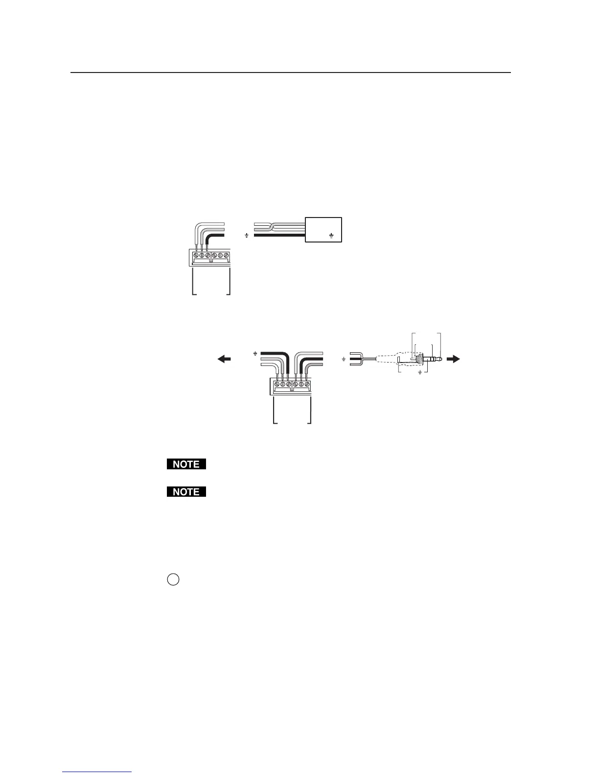
Use the following illustrations as a wiring guide. Wiring will vary depending
on the projector model. In most cases the drivers are bidirectional, but
sometimes only the transmit (Tx) and ground connections will be needed for
projector control. For bidirectional RS-232 communication, the transmit,
ground, and receive pins must be wired at both the switcher and the projector.
Projector
Panel
MLC 226
Bottom Panel
PROJECTOR
RS-232/IR
Tx/IR
Rx
GROUND
PWR SNS
GROUND
+12V OUT
Ground ( )
Receive (Rx)
Transmit (Tx)
Ground ( )
Receive (Rx)
Transmit (Tx)
Bidirectional
MLC 226
Bottom Panel
PROJECTOR
RS-232/IR
Tx/IR
Rx
GROUND
PWR SNS
GROUND
+12V OUT
Transmit (Tx)
Receive (Rx)
Ground ( )
To a
projector
or display
+12VDC
Ground ( )
Power
sense
Sleeve ( )
Ring
(signal)
Tip (+12 V)
3.5 mm Stereo Plug
To an Extron
Power Sensor
(60-271-01)
Each projector or display may require different wiring. For details, refer to the
manual that came with the projector.
Maximum distances from the MLC to the device being controlled may vary up
to 200 feet (61 m). Factors such as cable gauge, baud rates, environment, and
output levels (from the switcher and the device being controlled) all affect
transmission distance. Distances of about 50 feet (15 m) are typically not a
problem. In some cases the MLC may be capable of transmitting and
controlling a given device via RS-232 up to 250 feet (76 m) away, but the
RS-232 response levels of that device may be too low for the MLC to detect.
2
CM/IR/SCP port — You can connect up to four Extron control modules
(IRCMs, ACMs, RCMs), one Extron IR Link infrared signal repeater, and/or
an Extron SCP 226 control pad to this port to allow remote control of the
MLC 226 controller or other items. A maximum of six devices can be
connected to this port. Use the following diagram as a wiring guide.
The SCP 226 replicates the MLC’s front panel controls. The SCP 226 and the
IR Link can receive IR signals from an optional IR 402 remote control and
send them to the controller. Control modules can be used (once the MLC is
set up) to control VCRs, DVD players, tape decks, a projector lift, or screen
control. Refer to the appropriate device’s user’s manual.
The control modules, IR Link, and SCPs can be daisy chained, as shown in the
following diagram. Extron Comm-Link cable is recommended for these
connections.