2-7MLC 226 Series • Installation: Labeling, Cabling, Mounting
PRELIMINARY
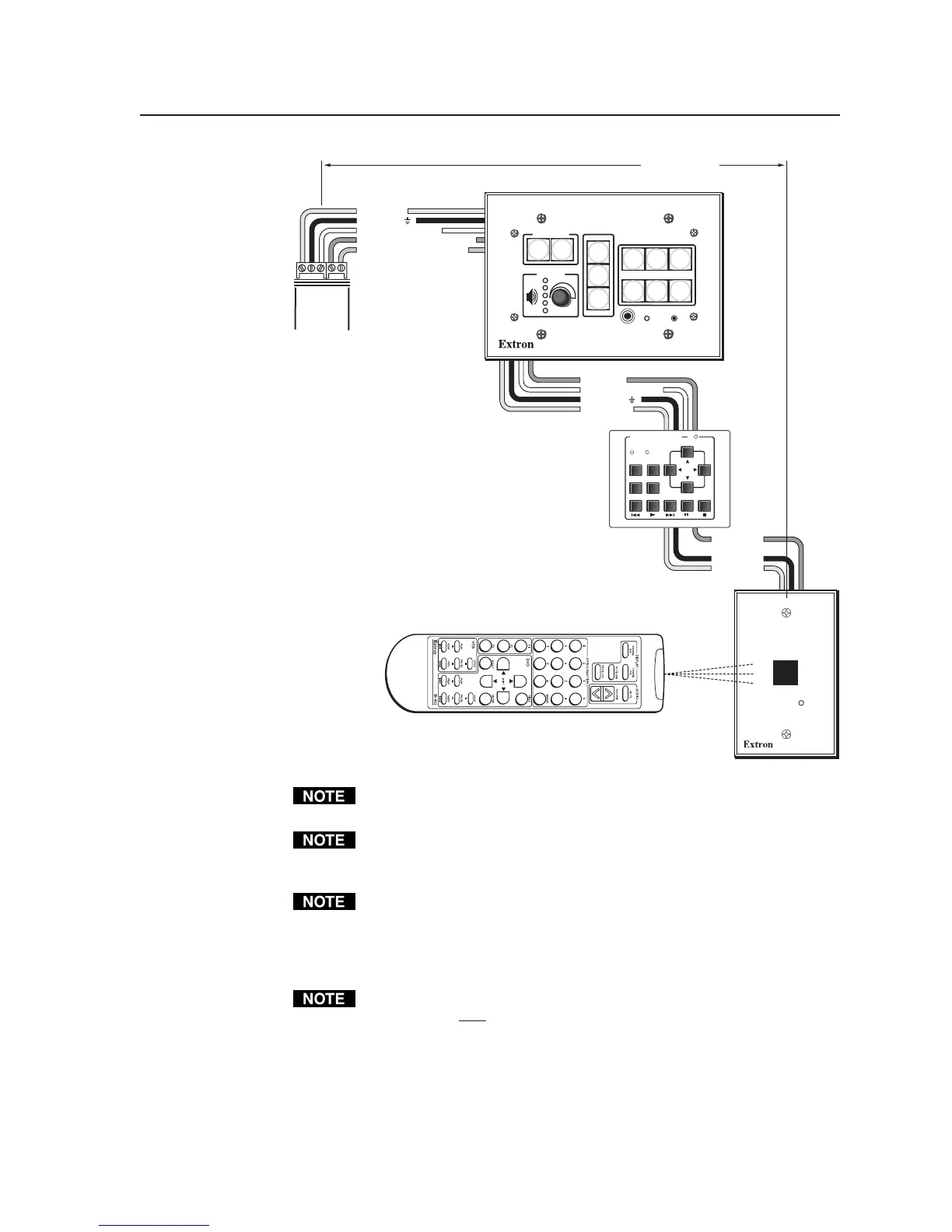
MLC 226
Bottom
Panel
CM/ IR SCP
A B C D E
+12V OUT
GROUND
CONT MOD
IR IN
SCP COM
E
D
C
B
A
SCP communication (IR)
Modulated IR (from IR Link)
Ground ( )
IRCM, ACM, RCM
+12 VDC
D
C
B
A
IR Link
Maximum =
2 SCPs
Per System
Maximum =
4 Control
Modules
(4 Module
Addresses)
Maximum =
1 IR Link
Ground ( )
IRCM/ACM/RCM
+12 VDC
D
B
A
IR Link
Ground
+12 VDC
DVD & VCR CONTROL
PLAY NEXT/FWD PAUSE STOP
TUNER
Tx
PREV/REW
ENTER
TITLE MENU
TV/VCR
DVD VCR
IRCM-DV+
SCP 226
IR Link
SIGNAL
IR LINK
PROJECTOR
SCP 226
1
2
3
4
5
6
VOLUME
CONFIG
IR
ON
OFF
LIGHT
ON
LIGHT
OFF
LAPTOP
VCR
DVD
PC
AUX
VIDEO
LECTERN
PC
AUTO
IMAGE
200' (61 m) max.
The maximum total distance between the MLC 226 and a connected device is
200' (61 m).
This port provides up to 12 VDC for powering the SCP control pad or other
devices. The automatic current protection circuit for this port limits the draw
to 0.5 amperes.
If an IRCM/RCM/ACM is to be used in an MLC/SCP system, the control
modules connected to the SCP must be of the same kind/model and must be
addressed identically to the modules that are connected to the MLC. Refer to
the appropriate control module user’s manual for instructions on addressing
the control modules.
Any SCP control pad or control modules (CM, IRCM, ACM, RCM) used
with the MLC
will be affected by front panel security lockout (executive mode)
status changes.