BCSD-42/116 Digital Brushless AC Servo Drive system - Ref. 1809
3.2.4. Interface Circuit
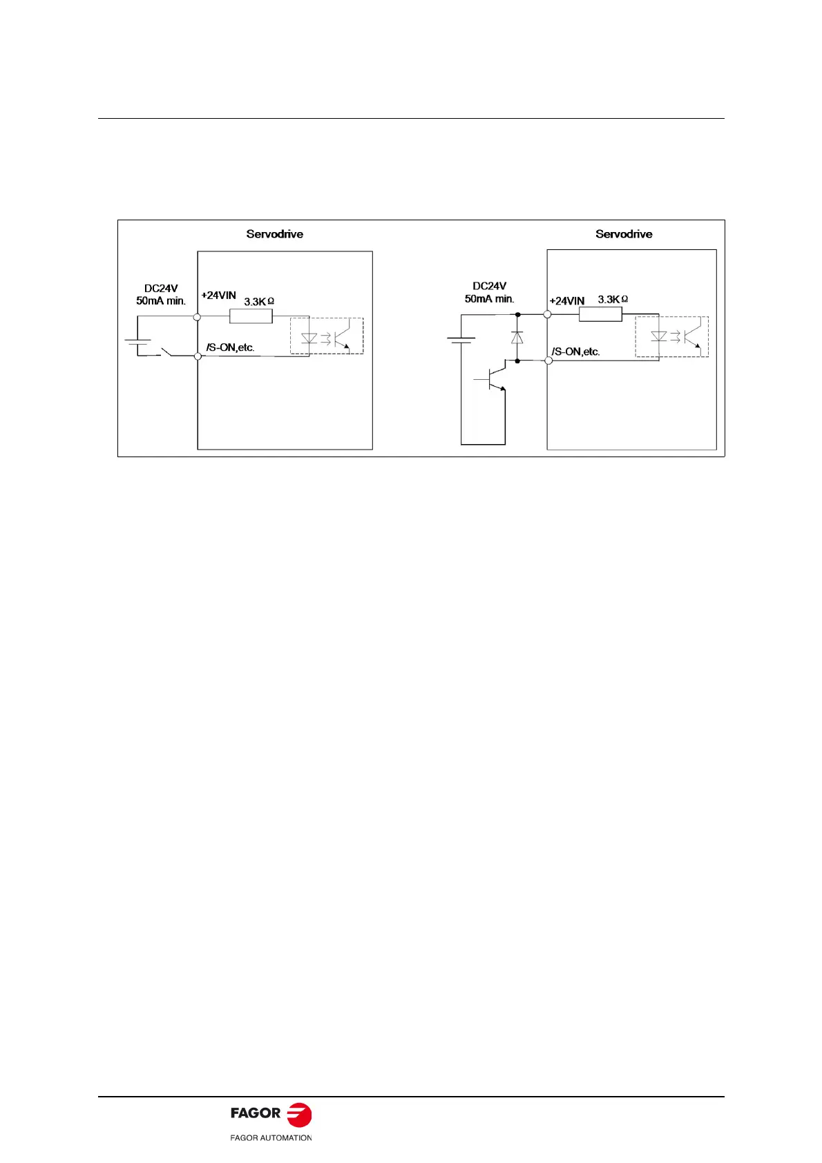
This section shows examples of servodrive I/O signal connection to the host controller.
• Interface for sequence input circuit.
The sequence input circuit interface connects through a relay or open-collector transistor circuit. Select
a low-current relay otherwise a faulty contact will result.
• Interface for line driver output circuit.
The amount of two-phase (phase A and phase B) pulse output signals (PAO, /PAO, PBO, /PBO) and
zero-point pulse signals (PCO, /PCO) are output via line-driver output circuits. Normally, the servodrive
uses this output circuit in speed control to comprise the position control system at the host controller.
Connect the line-driver output circuit through a line receiver circuit at the host controller.
• Interface for sequence output circuit.
Photocoupler output circuits are used for Servo Alarm (ALM), Servo Ready (S-RDY), and other se-
quence output signal circuits. Connect a photocoupler output circuit through a relay circuit.
 Loading...
