BCSD-40/116 Digital Brushless AC Servo Drive system - Ref. 1809
3.2.2. I/O Signal Names and Functions
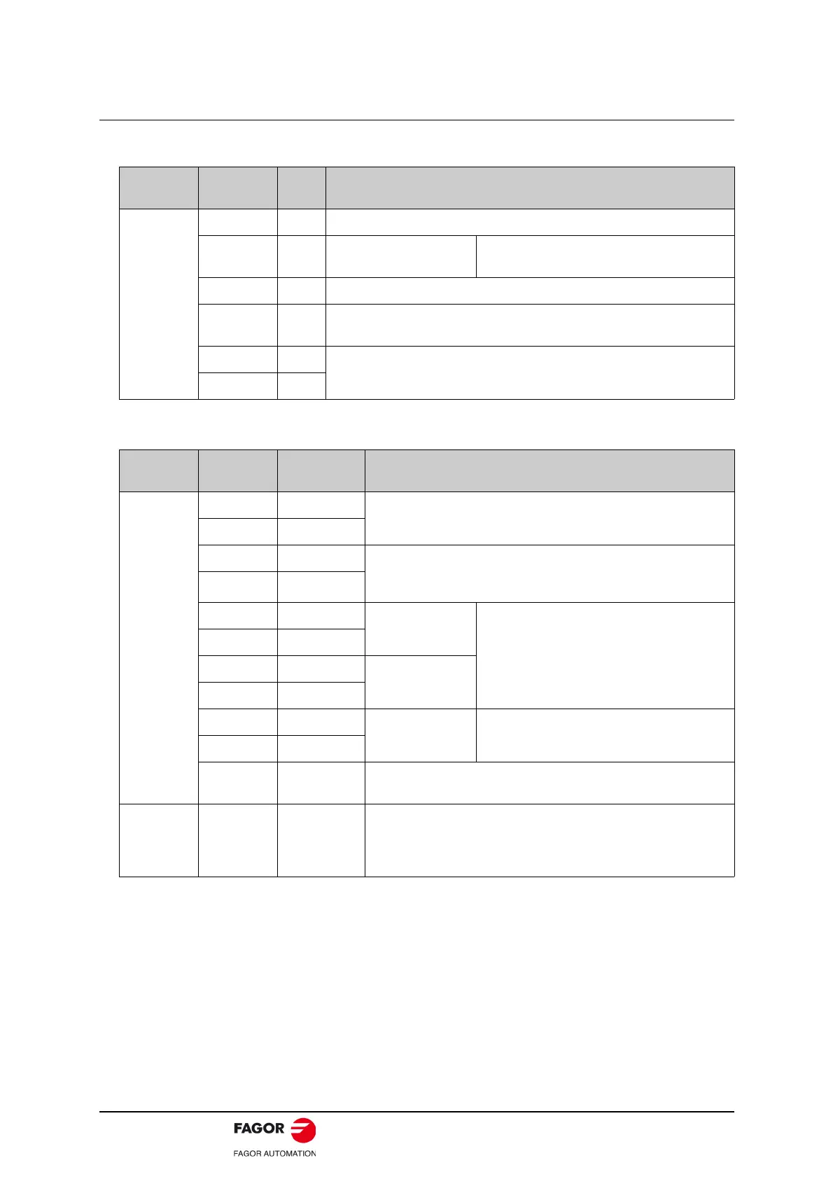
• Input Signals.
• Output Signals.
Control
Mode
Signal
Name
Pin
No.
Function
Speed
/S-ON 14 Servo ON: Turns the servomotor on.
P-OT
N-OT
16
17
Forward run prohibited
Reverse run prohibited
Overtravel prohibited:
Stops servomotor when OFF.
/ALM-RST 39 Alarm reset: Releases the servo alarm state.
DICOM 13
Control power supply input for I/O signals: Provide the +24 V DC power
supply.
VREF+ 1
Speed reference input: ±10 V.
VREF- 2
Control
Mode
Signal
Name
Pin No. Function
Speed
ALM+ 7
Servo alarm:
Turns off when an error is detected.
ALM- 8
/S-RDY+ 9 Servo ready:
ON if there is no servo alarm when the control/main circuit power
supply is turned ON.
/S-RDY- 10
PAO+ 20
Phase-A signal
Converted two-phase pulse (phases A and B)
encoder output.
PAO- 21
PBO+ 22
Phase-B signal
PBO- 23
PCO+ 24
Phase-C signal Zero-point pulse (Phase-C) signal.
PCO- 25
FG Shell
Connected to frame ground if the shield wire of the
I/O signal cable is connected to the connector shell.
Reserved -
4, 18, 19, 29,
35, 36, 37, 38,
43, 44, 45, 47,
49.
Not used.
 Loading...
