BCSD-58/116 Digital Brushless AC Servo Drive system - Ref. 1809
4.3.3. Setting the Overtravel Limit Function
The overtravel limit function forces movable machine parts to stop if they exceed the allowable range of
motion and turn ON a limit switch.
1. Connecting the overtravel signal.
To use the overtravel function, connect the following overtravel limit switch to the corresponding pin
number of servodrive CN1 connector correctly.
CAUTION
When using the servomotor on a vertical axis, the workpiece may fall in the overtravel condition.
To prevent this, always set the zero clamp after stopping with Pn004.0=5.
(2) Enabling/Disabling the Overtravel Signal.
A parameter can be set to disable the overtravel signal. If the parameter is set, there is no need to
wire the overtravel input signal.
Type
Signal
Name
Pin No. Setting Meaning
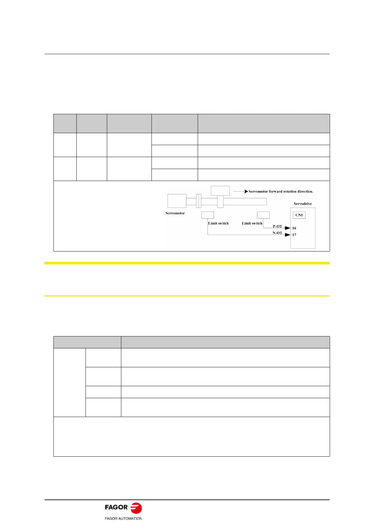
Input P-OT
CN1-16
(factory setting)
ON (low level) Forward rotation allowed. (Normal operation status.)
OFF (high level) Forward rotation prohibited. (Forward overtravel)
Input N-OT
CN1-17
(factory setting)
ON (low level) Reverse rotation. (Normal operation status.)
OFF (high level) Reverse rotation prohibited. (Reverse overtravel)
Connect limit switches as shown
below to prevent damage to the
devices during linear motion.
Rotation in the opposite direction is
possible during overtravel.
For example, reverse rotation is
possible during forward overtravel.
Parameter Meaning
Pn000
b.
0
Inputs the forward rotation prohibited (P-OT) signal from
CN1-16 (factory setting).
b.
1
Disables the forward rotation prohibited (P-OT) signal. (Allows constant forward
rotation.)
b.
0 Inputs the reverse rotation prohibited (N-OT) signal from CN1-17. (factory setting)
b.1
Disables the reverse rotation prohibited (N-OT) signal. (Allows constant reverse
rotation.)
- Applicable control modes: Speed control.
- After changing these parameters, turn OFF the main circuit and control power supplies and then turn them
ON again to enable the new settings.
- A parameter can be used to re-allocate input connector number for the P-OT and N-OT signals. Refer to 3.2.2
I/O Signal Names and Functions.