Digital Brushless AC Servo Drive system - Ref. 1809 BCSD-41/116
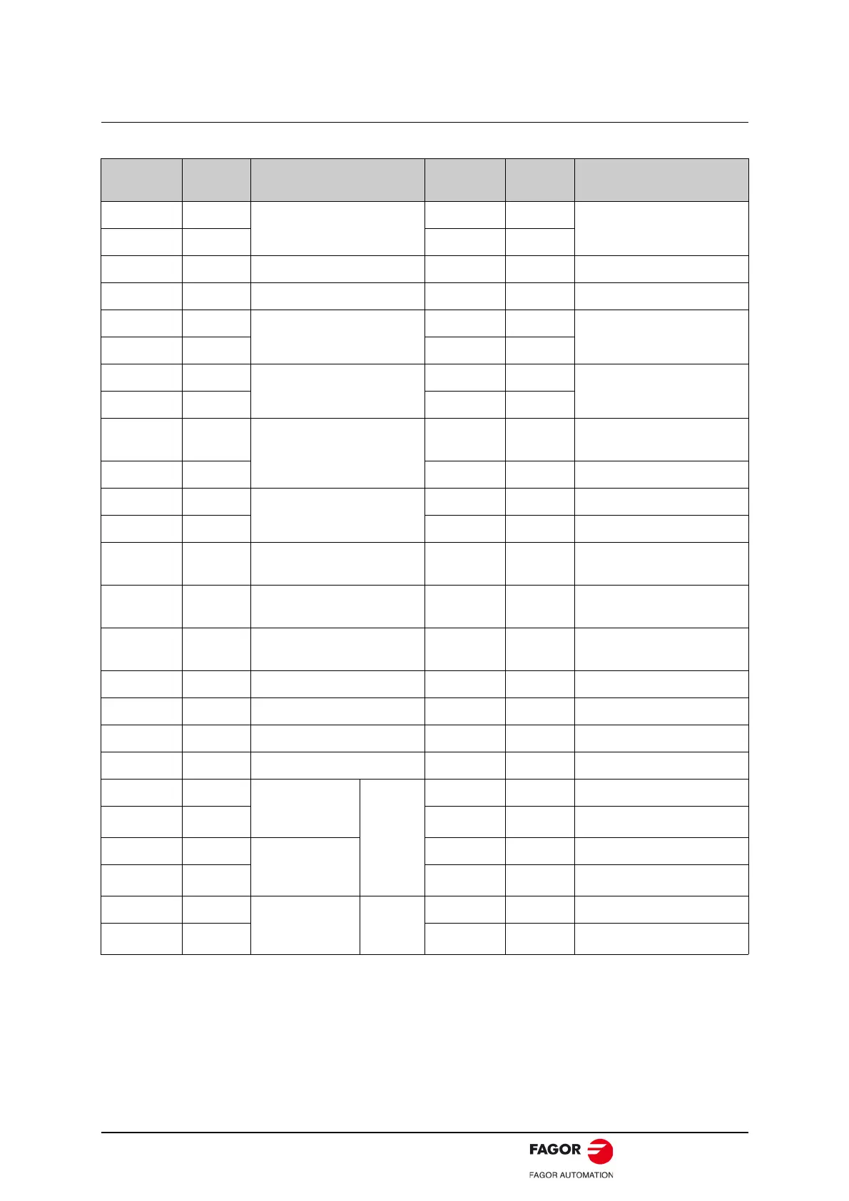
3.2.3. I/O Signal Connector (CN1) Terminal Layout
Note: The functions allocated to the following input and output signals can be changed by using the
parameters.
• Input signals: /S-ON, /P-CON, P-OT, N-OT, /ALM-RST, /CLR, /PCL, /NCL, SHOM, ORG.
• Output signals: /TGON, /S-RDY, /COIN, /HOME.
Please refer to A.3 Parameters in details for detailed information.
Terminal
No.
Name Function
Terminal
No.
Name Function
1VREF+
Speed reference input: ±10 V
26 T-REF+
Torque reference input: ±10 V
2 VREF- 27 T-REF-
3 DGND DGND 28 DGND DGND
4 - Reserved 29 - Reserved
5/TGON+
Running signal output
30 PULS+
Reference pulse input
6/TGON- 31PULS-
7ALM+
Servo alarm
32 SIGN+
Reference sign input
8ALM- 33SIGN-
9 /S-RDY+
Servo ready
34 PPI
Open collector reference
power supply
10 /S-RDY- 35 - Reserved
11 /COIN+
Positioning completion
36 - Reserved
12 /COIN- 37 - Reserved
13 DICOM
I/O signal power suply.
24 V DC
38 - Reserved
14 /S-ON Servo ON 39
/ALM-
RST
Alarm reset
15 /P-CON P/PI control input 40 /CLR
Position error pulse clear
input
16 P-OT Forward run prohibit input 41 /PCL Forward torque limit input
17 N-OT Reverse run prohibit run 42 /NCL Reverse torque limit input
18 - Reserved 43 - Reserved
19 - Reserved 44 - Reserved
20 PAO+ PG dividing
pulse output
phase A
PG
dividing
pulse
output
45 - Reserved
21 PAO- 46 DGND DGND
22 PBO+ PG dividing
pulse output
phase B
47 - Reserved
23 PBO- 48 DGND DGND
24 PCO+ PG dividing
pulse output
phase C
Zero-
point
pulse
49 - Reserved
25 PCO- 50 DGND DGND
 Loading...
