Digital Brushless AC Servo Drive system - Ref. 1809 BCSD-69/116
4.5. Other Output Signals
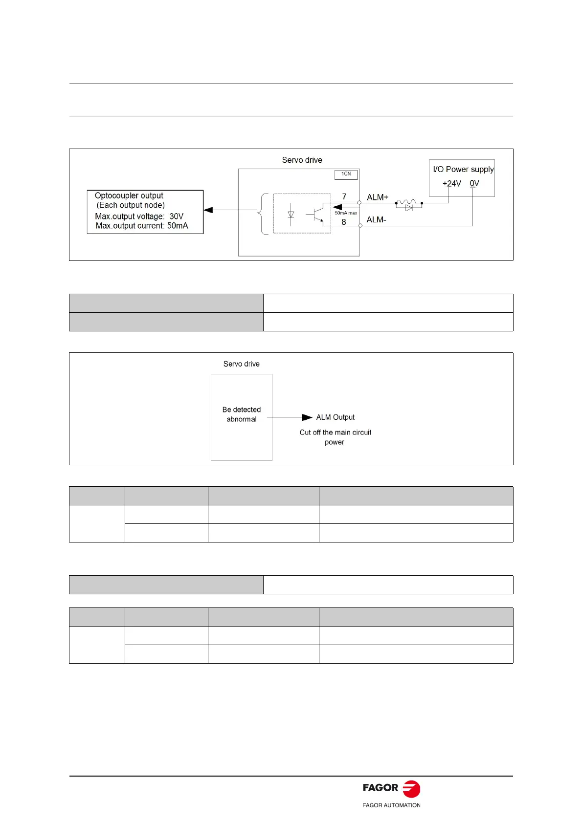
4.5.1. Servo alarm output
The following diagram shows the right way to connect Alarm Output.
External +24 V I/O power supply is required, since there is no +24 V power supply available inside servo
drive.
The signal outputs when servodrive is detected abnormal.
Normally, the external circuit consists of /ALM should be able to switch off power of servo drive.
When “servo alarm (ALM)” happens, always remove alarm reasons first, and then turn the input signal
"/ALM-RST" to ON position to reset alarm status.
Normally, the external circuit can switch off power supply of servo drive when alarm occurs. When servo
drive is re-switched on, it removes alarm automatically, so normally alarm reset signal is not required to
be connected.
In addition, alarm reset are enabled with panel operator.
Note:
When alarm occurs, always remove alarm reasons before resetting alarms.
Output ALM+ 1CN- 7 Servo alarm output
Output ALM- 1CN- 8 Servo alarm output uses grounding signal
Signal Status Output level Comments
ALM
ON 1CN-7:“L” level Normal state
OFF 1CN-8:“H” level Alarm state
Input /ALM-RST 1CN- 39 alarm reset input
Signal Status Output level Comments
/ALM-RST
ON 1CN-39:“L” level Reset servo alarm
OFF 1CN-39:“H” level Do not reset servo alarm
 Loading...
