INSTALLATION MT100 Multipoint Flow Meter
The above precautions are minimum requirements to be used. The complete use of ESD precautions can be found in the U.S. Department
of Defense Handbook 263.
Verify Serial Numbers
Verify that the equipment tags on the remote enclosure and associated flow transmitter have matching serial numbers.
Refer to the appropriate drawing in APPENDIX A, page 97 for nameplate tagging information.
Prepare or Verify Flow Element Location
The flow element location should have been previously determined before the time of order. Mounting the flow element in a position
different than originally determined may cause reading errors. Prepare the process pipe for installation, or inspect the already prepared
location to ensure that the instrument will fit into the system. The flow element length (U-length) is customer specified. The recommended
diameter for the clearance hole needed to mount the flow element is specified in the top assembly drawing in APPENDIX A, page 97.
Verify Dimensions
Verify the customer specified flow element U-length and instrument mounting interface dimensions are correct for the application.
Referencing the equipment dimensions in the appropriate top assembly drawing in APPENDIX A, compare the instrument hardware and
the process interfaces for fit.
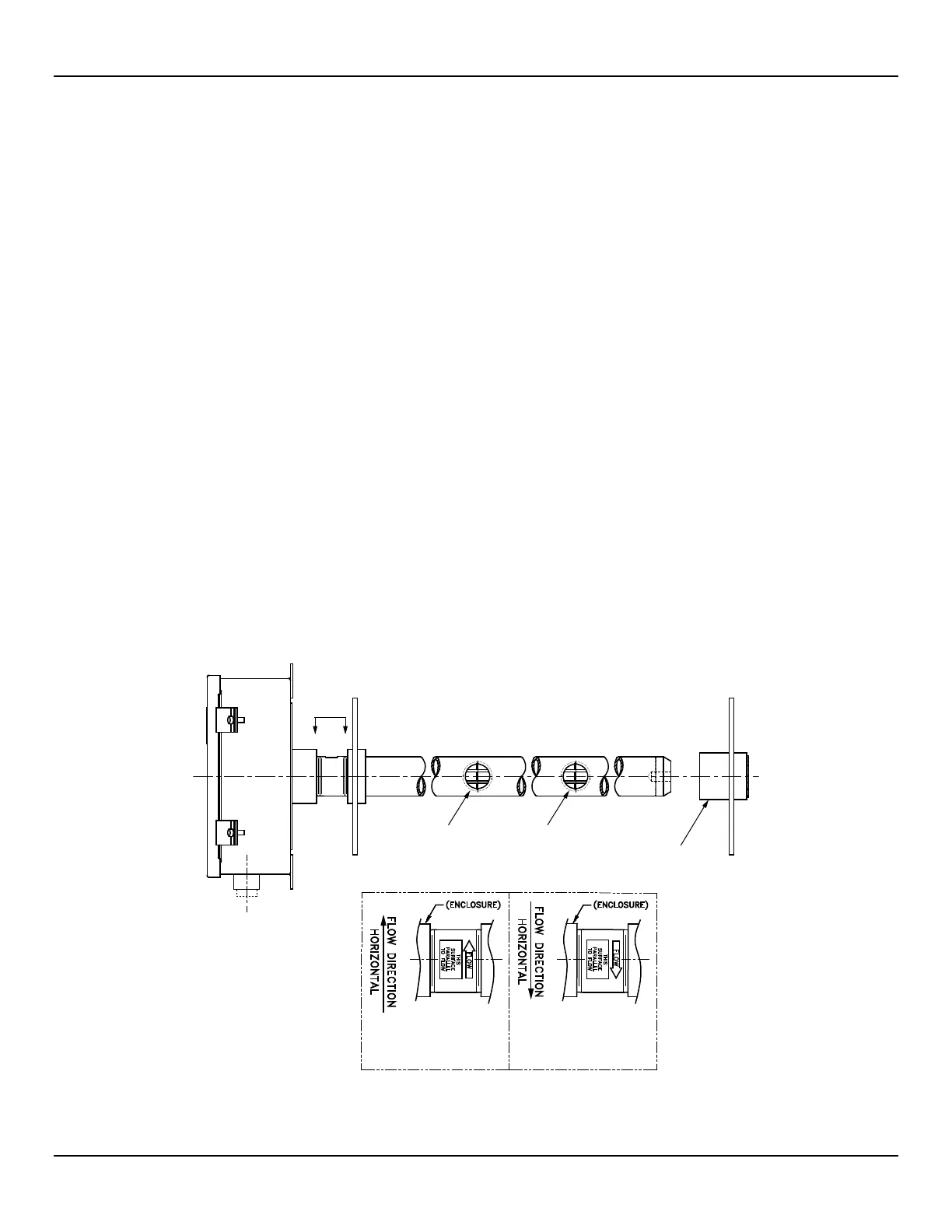
Verify Flow Direction for Flow Element Orientation and Placement
The flow element comes with a flat surface machined on the flow element near the enclosure. This flat surface is known as the reference
(or orientation) flat, which includes a flow arrow etched on its surface to indicate flow direction. See Figure 1 and Figure 3 below.
Align the flow element with the flat parallel to the flow and the flat’s arrow pointing in the same direction as the flow. Failure to correctly
install the flow element reduces the accuracy of the flow meter. Refer to APPENDIX A for specific information.
A flow element assembly has its reference flat in a particular location with its arrow pointing in a certain direction
depending on its configuration. Verify that the flow element assembly is the correct configuration for its installed
location. Duct mount configurations, for example, can include side/bottom/top mount and horizontal left/right flow or
vertical up/down flow. Refer to
APPENDIX A for configuration information specific to the unit’s serial/tag number.
C01270-1-1
VIEW B - B
SCALE: NONE
(LEFT TO RIGHT
CONFIGURATION)
VIEW B - B
SCALE: NONE
(RIGHT TO LEFT
CONFIGURATION)
TYPICAL DUCT MOUNT
END SUPPORT
SENSE PT 1
SENSE PT 2
B B
Figure 1 – MT100M: Multipoint Flow Element Showing Flat Area, Duct Mount (Side Mounted Horizontal Configuration Shown)
Fluid Components International LLC 6