MT100 Multipoint Flow Meter INSTALLATION
Wiring
Table 2 below shows the smallest copper wire (maximum AWG number) that can be used for the listed cabling. Contact FCI concerning
greater distances than those listed in the chart. Refer to APPENDIX A, page 97 for specific wiring/cabling information.
Table 2 – Interconnecting Cable Minimum Conductor Size
Maximum Distance for AWG [mm
2
Connection
1
RS-485 (14-30 AWG) [2.0809-0.0509]
OUNDATION
FF-844 H1 (14-30 AWG) [2.0809-0.0509]
2
RS-485 (14-30 AWG) [2.0809-0.0509]
Notes: 1. Requires a shielded cable. The shield is connected to the GND in the transmitter enclosure. The other end of
the shield is left floating (no connection to the flow element enclosure).
2. Transmission speed determines maximum cable length and vice versa:
9.6 kbps = 3940 ft/1200 m, 19.2 kbps = 3940 ft/1200 m, 45.45 kbps = 3940 ft/1200 m, 93.75 kbps = 3940 ft/1200 m,
187.5 kbps = 3280 ft/1000 m, 500 kbps = 1310 ft/400 m, 1500 kbps = 656 ft/200 m, 3000 kbps = 328 ft/100 m,
6000 kbps = 328 ft/100 m, 12000 kbps = 328 ft/100 m.
Conduit Routing (If applicable)
Working with conduit and pulling cables after installation can cause damage to the electronic components.
Disconnect both ends of cabling before moving conduit.
Protection of the flow transmitter from moisture is important. Keep the entry of the conduit into the enclosures in the downward direction so
condensed moisture that collects in the conduit will not drain into the enclosure. FCI recommends sealing off the conduit with a silicone
encapsulant/potting compound to prevent moisture from entering the enclosures.
See APPENDIX A for specific information on cable entry type(s) and locations for sensors, power input and 4-20 mA output.
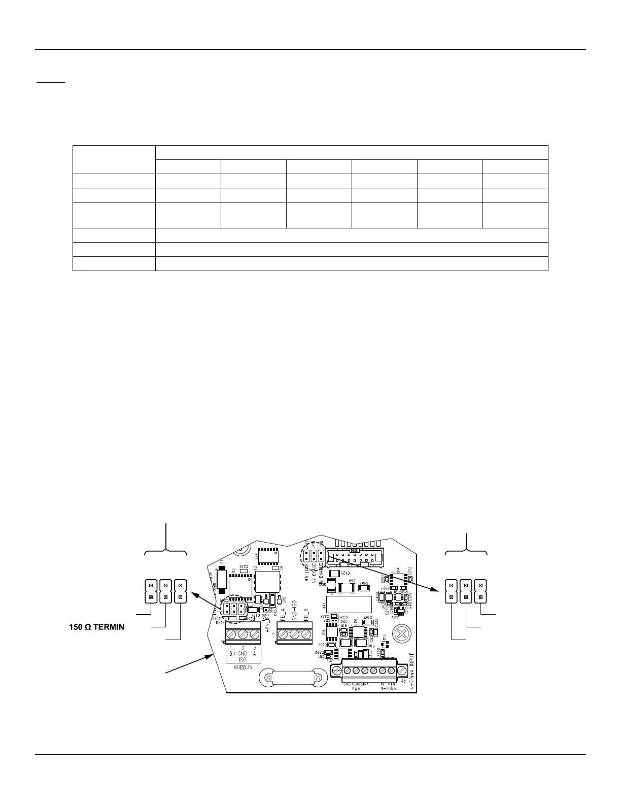
Configuration Jumpers (Modbus/Fieldbus/PROFIBUS)
When wiring the instrument for Modbus/Fieldbus/PROFIBUS make sure the instrument is properly configured as shown in Figure 20
below. Refer to Modbus on page 28 and Foundation Fieldbus/PROFIBUS (Option) on page 29 for details.
MODBUS LINE CONFIG. PROFIBUS/FIELDBUS ADD-ON CARD
DIAGNOSTIC/TEST
JP13
JP14
JP15
J3
JP20
JP19
JP18
B+ LINE PULLUP
ATION
A- LINE PULLDOWN
J25 J26
#SIM_ENABLE
#NV_ERASE
#HW_LOCK
SB4 MAIN BOARD
C01420-1-1
Figure 20 – Bus Configuration 0.100" Jumper Headers
Fluid Components International LLC 23