TROUBLESHOOTING MT100 Multipoint Flow Meter
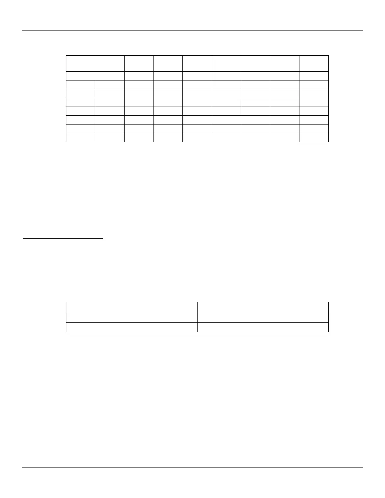
Table 26 – Flow Element Resistance (In Ohms) at the Local Enclosure (MT100M, Multipoint Sensor Application)
1 2 3 4 5 6 7 8
2
2
2
1
2
2
2
2
2
1
2
2
1
2
2
2
2
2
1
2
3
3
Notes: 1. Theoretical zero-ohm table values are influenced by sensor cable length, which typically adds <2 Ω.
2. Resistances are approximate for a sensor temperature of 70 °F (21 °C).
3. Heater resistance tolerance is ±10 Ω.
If the instrument has been on for some time, the resistance of the active RTD will be greater than the reference RTD.
If the instrument has been off for some time, the resistance of the active RTD will be the same as the reference RTD.
If the measured resistances correspond to Table 25 or Table 26, but not to Table 24, then the cable is probably defective. Replace the
cable and recheck resistances. If the resistances are still off, contact Customer Service. Plug in the TS2 connectors and reattach the
cables when troubleshooting is complete.
If the measured values do not correspond to Table 24, Table 25 or Table 26, then the flow element is defective. Contact Customer Service.
Verification of the Electronics
Transmitter Power Supply
Using a DMM set to DC volts (V) check the voltages shown in the table below. Take the readings from J13, a white 1 x 6 header pin
connector on the SB4 main board near the microSD card socket. Silkscreen markings on the board identify the J13 pins.
Be careful not to short the J13 header pins when taking the voltage readings.
Table 27 – Instrument Power Supply Voltages
Expected Power Supply Voltage
Digital 5 VDC: J13-2 to J13-5
1
(Gnd) +4.75 V to +5.25 V
Analog 24 VDC: J13-1 to J13-5
1
Note: 1. J13-4, J13-5, and J13-6 are all ground pins.
If the voltage measurements are within the range shown in the table, the power supply is functioning properly.
Transmitter Circuit Calibration Check (Delta R Verification)
Equipment Needed:
• FES-200 Flow Element Simulator with MT100-specific cable
• Digital Multimeter
• Delta R Calibration Data Sheet (serial number specific by instrument and group)
• Precision 250 ohm resistor (recommended)
Alternate Tool for FES-200:
• 2 ea. Precision Decade Resistance Box, 0.1% (1 kΩ large step, 0.01 Ω small step)
If the flow meter’s parameters have been changed, calibrations may be inaccurate or factory authorized changes
have been made. Consult a factory service representative.
Fluid Components International LLC 92