MT100 Multipoint Flow Meter OPERATION
3 OPERATION
Introduction
The flow meter has been configured and calibrated to custom specifications. Each flow meter contains distinct operating limits and units of
measurement. This section shows how to determine and manipulate the configuration of the flow meter.
The flow transmitter contains electrostatic discharge (ESD) sensitive devices. Use standard ESD precautions when
handling the flow transmitter. Refer to the Use Standard ESD Precautions discussion, page 5.
Startup and Commissioning
Verify the wiring and then apply power to the flow meter. As the instrument boots the LCD shows the FCI logo with a progress bar below it that fills
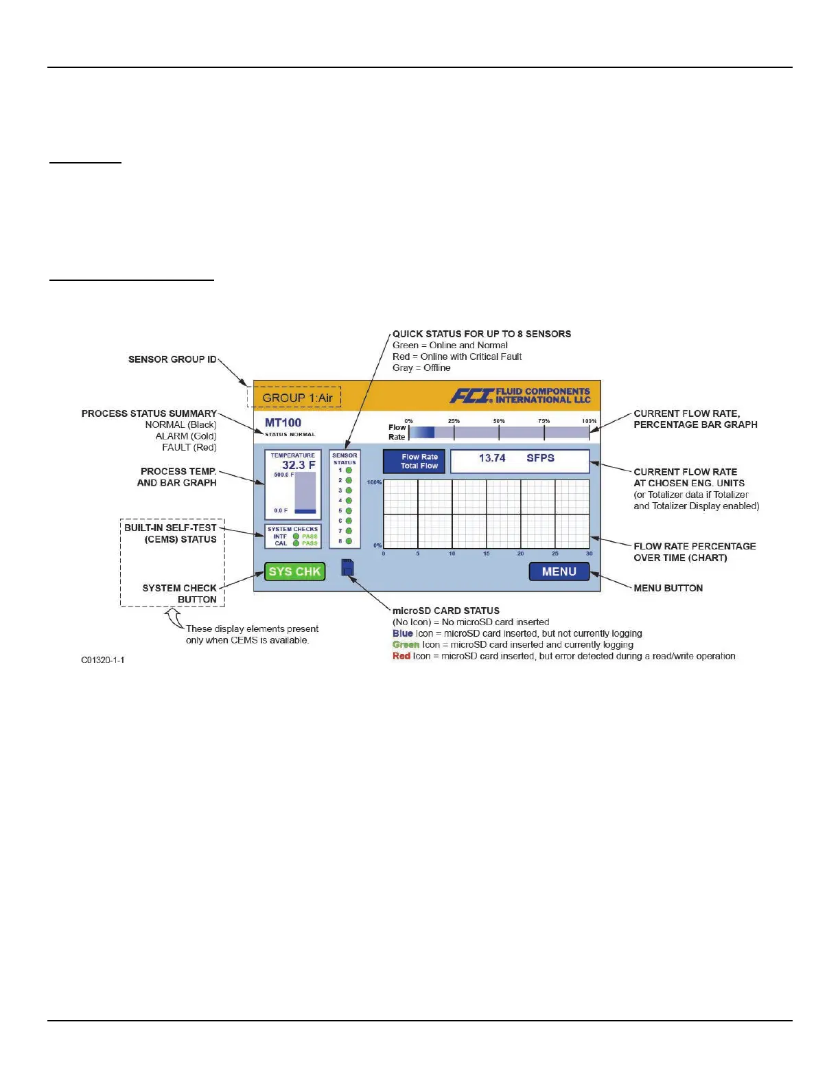
up from left to right. After the progress bar completes (about 30 seconds) a screen similar to that shown in Figure 30 below is displayed.
Figure 30 – MT100 Normal Process Display Screen
The process display screen shows key information at a glance. Moreover, the instrument LCD touchscreen functions as a basic HMI
(Human-machine Interface) setup tool. Open the enclosure door and tap MENU to access the HMI setup menu (refer to Using the
Touchscreen Display, page 34). See APPENDIX C, page 147 for an overview of the system’s hierarchal menu structure.
Wait a minimum of 10 minutes for flow meter to stabilize. The output signal indicates the media flow. There is no operator action needed
because the flow meter operates from the factory settings. There are no special instructions for shutdown of the flow meter; just remove
the operating power.
If the output signal is zero, is out-of-range for the expected values or is obviously not right then turn power OFF and refer to
TROUBLESHOOTING, page 87 for help with finding the problem.
Operator Interaction
Once set up, there is little need for interaction between the operator and flow meter. The flow meter is fully automatic when it operates in
the normal monitor mode. FCI advises the use of factory default settings with which the flow meter was ordered. Do not reset the flow
meter's operating values by trial and error. A slow, blinking green LED on the SB4 main board in front of the Sensor 2 connector block
provides a quick status check that all is normal.
The output signal provides an instant readout of mass flow. The output signal shows only the flow rates between the upper and lower limits
of the calibrated range. For zero-based instruments the output signal will indicate zero flow (4 mA) whenever the flow rate is below the
calibrated lower limit. For non-zero-based instruments the output signal will read the minimum specified flow rate.
Fluid Components International LLC 33