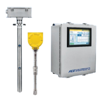
MT100 Multipoint Flow Meter 06EN003460 Rev. C
List of Figures
Figure 1 – MT100M: Multipoint Flow Element Showing Flat Area, Duct Mount (Side Mounted Horizontal Configuration Shown)...........6
Figure 2 – MT100M: Multipoint Flow Element Showing Flat Area, Flange Mount ....................................................................................7
Figure 3 – MT100S: Single Point Flow Element Showing Flat Area, Flange Mount.................................................................................7
Figure 4 – Duct Flange Mounting, Dimensions, and Mounting Hardware.................................................................................................9
Figure 5 – Duct Flange Mounting, End Support Hardware (Optional) ....................................................................................................10
Figure 6 – Alternative Duct Flange Mounting, Dimensions and Mounting Hardware..............................................................................11
Figure 7 – Alternative Duct Flange Mounting, End Support Hardware (Optional) ..................................................................................12
Figure 8 – Single Point, Fixed RF Flange Process Connection..............................................................................................................13
Figure 9 – Multipoint, RF Flange Process Connection (High Temp Shown) ..........................................................................................14
Figure 10 – Multipoint Flanged Sensor Probe Example Installation .......................................................................................................15
Figure 11 – Multipoint Flanged Probe End Support Detail......................................................................................................................15
Figure 12 –Single Point, Fixed 1" Welded NPT Process Connection.....................................................................................................16
Figure 13 – Multipoint, 2" NPT Process Connection (Low Temp Shown)...............................................................................................16
Figure 14 – Compression Fitting Mounting Dimensions .........................................................................................................................17
Figure 15 – Compression Fitting Process Connection (Optional Flange Shown)...................................................................................18
Figure 16 – Low Pressure Retractable Packing Gland, NPT Process Connection Shown.....................................................................19
Figure 17 – Medium Pressure Retractable Packing Gland, Flange Process Connection Shown...........................................................20
Figure 18 – Multiple Single Point Probe Installation (Packing Gland Shown).........................................................................................21
Figure 19 – MT100 Remote Transmitter Enclosure Outline Drawing .....................................................................................................22
Figure 20 – Bus Configuration 0.100" Jumper Headers .........................................................................................................................23
Figure 21 – MT100 Electronics Enclosure Label ....................................................................................................................................24
Figure 22 – Flow Element Connections ..................................................................................................................................................25
Figure 23 – Input Power and I/O Connections........................................................................................................................................26
Figure 24 – Single Connection and Multidrop HART Setups..................................................................................................................27
Figure 25 – Modbus Wiring.....................................................................................................................................................................28
Figure 26 – Fieldbus/PROFIBUS Wiring.................................................................................................................................................29
Figure 27 – Sink Output ..........................................................................................................................................................................30
Figure 28 – Source Output......................................................................................................................................................................30
Figure 29 – Cable Gland Installation.......................................................................................................................................................32
Figure 30 – MT100 Normal Process Display Screen..............................................................................................................................33
Figure 31 – microSD Card Socket J7 Location.......................................................................................................................................34
Figure 32 – SD Card Data Logging Example Screen (MT100 Configuration Software) .........................................................................35
Figure 33 – Chart: Flow Output Over Time with Various Flow Damping Values ....................................................................................36
Figure 34 – CEMS Option, Specific HMI Front Panel Display Elements ................................................................................................37
Figure 35 – Process Screen Showing Touch Screen Calibration Required ...........................................................................................39
Figure 36 – Zero Based Calibration ........................................................................................................................................................42
Figure 37 – Field Communicator Easy Upgrade Utility, Import DD.........................................................................................................44
Figure 38 – Extended Operating Mode Status on HMI Front Panel Display (EGS Shown)....................................................................72
Figure 39 – Connections for External Input Flow Adjust (EIA)................................................................................................................73
Fluid Components International LLC v

 Loading...