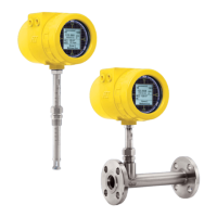
GENERAL ST100 Series Flow Meter
4 Fluid Components International LLC
ST100L In-line Style
– FP and – S Style Flow Element:
-40 °F to 250 °F [-40 °C to 121 °C]
Process Connection
Compression Fittings: Models ST100 and ST102 only
3/4” or 1” male NPT, stainless steel with adjustable Teflon ferrule or
metal ferrule; or flanged tapped and threaded for 3/4” fitting, ANSI
or DIN flanges
Compression fittings not available with 850 °F [454 °C] temperature
versions of ST100 or ST102
Retractable Packing Glands
Low pressure 50 psig [3,5 bar (g)] or medium pressure 500 psig
[34 bar (g)] with graphite or Teflon packing material; 1 1/4” male NPT
or ANSI or DIN flange
Teflon packing required when process media is ozone, chlorine or
bromine
Fixed Fittings / All Welded
1” male NPT, ANSI or DIN flange
Insertion Length
Field adjustable lengths:
1” to 6” [25 mm to 152 mm]
1” to 12” [25 mm to 305 mm]
1” to 21” [25 mm to 533 mm]
1” to 36” [25 mm to 914 mm]
1” to 60” [25 mm to 1524 mm]
Fixed lengths from 2.6” to 60” [66 mm to 1524 mm]
ST100L In-line Flow Tube
Flow element is calibrated and supplied as a spool-piece; options
include low flow injection tubes and built-in Vortab flow conditioners
for optimum low flow rangeability and performance
Size: 1” diameter tubing; 1”, 1 1/2” or 2” schedule 40 pipe
Length: 9 nominal diameters
Process Connections: Female NPT, male NPT, ANSI or DIN
flanges, or butt weld prepared
Option: Flanges sized for flow tube
Remote Transmitter Configurations: Transmitter may be
mounted remotely from flow element using interconnecting cable
(up to 1000’ [300 m])
STP Models: Additional Specifications on Pressure Sensor
Calibrated at nominal 70 °F [21 °C]
Zero/Span Shift: 0.83% full scale/100 °F [1.5% full scale/100 °C]
Zero Tolerance: ± 0.5% of full scale
Span Tolerance: ± 0.5% of full scale
Long Term Stability: ± 0.2% full scale per year
Maximum over Pressure:
50 psi, 100 psi [3,4 bar, 7 bar] versions 3.0 x rated rate range
500 psi, 1000 psi [34 bar, 70 bar] versions 2.0 x rated rate range
Minimum burst Pressure (all):
50 psi, 100 psi [3,4 bar, 7 bar] versions 40 x rated rate range
500 psi, 1000 psi [34 bar, 70 bar] versions 20 x rated rate range
Wetted Materials:
17-4 PH stainless steel diaphragm (not recommended for hydrogen
service; contact FCI for Model STP for use in hydrogen)
304 stainless steel fittings
Flow Transmitter/Electronics
Operating Temperature:
Single Point System: 0 °F to 140 °F [-18 ° to 60 °C]
Two Point System: 0 °F to 100 °F [-18 ° to 38 °C]
Input Power
AC: 85 Vac to 265 Vac, 50 Hz to 60 Hz
DC - Single Point System: 24 Vdc ± 20%
DC - Two Point System: 23.5 Vdc - 28 Vdc ± 20%
Power Consumption
AC: 85 to 265V = 10W, 1 Flow Element
13.1W, 2 Flow Element
DC: 24V = 9.6W, 1 Flow Element
13.2W, 2 Flow Elements
Outputs
Analog
Standard: Three (3) 4-20 mA*, 0-1kHz, or 0-10 kHz pulse/frequency
4-20 mA outputs are user assignable to flow rate, temperature
and/or if so equipped, pressure; outputs are user programmable to
full flow range or subsets of full flow range; pulse/frequency output
is user selectable as pulse for external counter/flow totalizer, or as
0-1 kHz or 0-10 kHz frequency representing flow rate
HART (comes standard with analog outputs, V7 compliant
* Outputs are isolated and have fault indication per NAMUR NE43
guidelines, user selectable for high (>21.0 mA) or low (<3.6 mA)
Digital
Standard: USB, Ethernet - Service and Configuration Ports Only
Optional: F
oundation Fieldbus H1, PROFIBUS PA or Modbus RS-485
FF Physical Parameters
Device Capacitance - Ci (in nF) = 0
Device Inductance - Li (in mH) = 1.01
Maximum Network Input Voltage - Ui (in V) = 32
Maximum Network Input Current - li (in mA) = 13
Auxiliary Inputs
One 4-20 mA input channel; used for FCI administered special
configurations to allow ST100 Series to accept inputs from external
devices such as gas analyzers, gas composition or pressure sensors
Enclosures
Main Transmitter / Electronics:
NEMA 4X, IP67; polyester powder coated aluminum; 4 conduit ports
threaded as 1/2” NPT or M20x1.5; 7.74” x 5.40” x 5.00” [196.6 mm x
137.2 mm x 127 mm]; stainless steel enclosure pending
Local Enclosure (Remote Configuration):
Model ST100L, Models ST100 and ST102 without packing gland
option:
NEMA 4X, IP67; polyester powder coated aluminum; 2 conduit ports
threaded as 1/2” NPT or M20x1.5; 3.75” x 4.00” x 3.24” [95 mm x
102 mm
x 82 mm]
Models ST100 and ST102 with medium pressure packing gland
option; ST110, ST112 and all STP Models:
NEMA 4X, IP67; polyester powder coated aluminum; 1 conduit port
threaded as 1” NPT or M20x1.5; 5.40” x 4.82” [137.2 mm x 122 mm]
Data Logger
User programmable for readings per time increment to a maximum
of 1 reading/second; removable, circuit board-mountable
2GB micro-SD (secure digital) memory card supplied; stores
approximately 21M readings in ASCII comma-separated format,

 Loading...