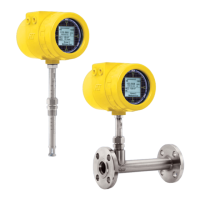
06EN003400 Rev. F ST100 Series Flow Meter
ii Fluid Components International LLC
Process Data Logging Configuration .....................................................................................................................................................................................................24
Process Data Log File Handling ............................................................................................................................................................................................................24
Remove microSD Card from the Instrument and Manually Transfer Files with a Card Reader ........................................................................................................... 24
Upload Selected Log File(s) to a PC Using a USB Cable and the ST100 Configuration Application .................................................................................................... 25
Internal Delta-R Resistor Check ................................................................................................................................................................................................................25
Running the Internal Delta-R Resistor Check .......................................................................................................................................................................................25
Analog Output Response to IDR Check .................................................................................................................................................................................................27
Extended Operation Modes ......................................................................................................................................................................................................................27
Basic ......................................................................................................................................................................................................................................................27
External Input Flow Adjust (EIA) ...........................................................................................................................................................................................................28
External ST100 Flow Input (EFI) ............................................................................................................................................................................................................29
Auto FE Calibration Group Switching (FCS) ..........................................................................................................................................................................................30
External Control Group Switching (EGS) ............................................................................................................................................................................................... 31
4 MAINTENANCE ............................................................................................................................................................................................................ .33
Calibration .................................................................................................................................................................................................................................................33
Electrical Connections ..............................................................................................................................................................................................................................33
Remote Enclosure .....................................................................................................................................................................................................................................33
Electrical Wiring .......................................................................................................................................................................................................................................33
Flow Element Connections .......................................................................................................................................................................................................................33
Flow Element Assembly ............................................................................................................................................................................................................................33
5 TROUBLESHOOTING ....................................................................................................................................................................................................35
Quick Check ...............................................................................................................................................................................................................................................35
General Function Check ............................................................................................................................................................................................................................36
Setup Verification .................................................................................................................................................................................................................................. 36
Application Verification ............................................................................................................................................................................................................................37
Equipment Needed ................................................................................................................................................................................................................................ 37
Check Serial Numbers ........................................................................................................................................................................................................................... 37
Check for Moisture ................................................................................................................................................................................................................................ 37
Check Application Design Requirements ..............................................................................................................................................................................................37
Verify Standard Versus Actual Process Conditions...............................................................................................................................................................................38
Check the Hardware .................................................................................................................................................................................................................................38
Troubleshooting the Flow Element........................................................................................................................................................................................................39
Integral Flow Element Resistance Table ...............................................................................................................................................................................................39
Remote Flow Element Resistance Table ...............................................................................................................................................................................................40
Check the Flow Element Voltages .........................................................................................................................................................................................................41
Verification of the Electronics ................................................................................................................................................................................................................... 42
Check the Flow Transmitter Power Supply Voltages ............................................................................................................................................................................42
Transmitter Circuit Calibration Check (Delta R Verification) .................................................................................................................................................................42
Equipment Needed ................................................................................................................................................................................................................................ 42
Alternate Tool for FES-200 .................................................................................................................................................................................................................... 42
Safety Instructions .................................................................................................................................................................................................................................... 42
Delta R Check ............................................................................................................................................................................................................................................42
Heater Current Check ................................................................................................................................................................................................................................43
Allowable Limits .......................................................................................................................................................................................................................................44
Output Verification using the ST100 Configuration Application ........................................................................................................................................................... 47
Defective Parts ..........................................................................................................................................................................................................................................47

 Loading...