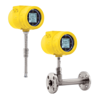
ST100 Series Flow Meter 06EN003400 Rev. F
Fluid Components International LLC iii
APPENDIX A OUTLINE DIMENSIONAL DRAWINGS .......................................................................................................................................................................49
APPENDIX B WIRING DIAGRAMS .....................................................................................................................................................................................................59
Figure B-1 – Integral: AC Input Power, Analog and HART Output ........................................................................................................................................................ 60
Figure B-2 – Remote: AC Input Power, Analog and HART Output ........................................................................................................................................................ 60
Figure B-3 – Integral: DC Input Power, Analog and HART Output ........................................................................................................................................................ 61
Figure B-4 – Remote: DC Input Power, Analog and HART Output ........................................................................................................................................................ 61
Figure B-5 – Integral: AC Input Power, Foundation Fieldbus Output ......................................................................................................................................................62
Figure B-6 – Remote: AC Input Power, F
oundation Fieldbus Output ......................................................................................................................................................62
Figure B-7 – Integral: DC Input Power, F
oundation Fieldbus Output ......................................................................................................................................................63
Figure B-8 – Remote: DC Input Power, F
oundation Fieldbus Output ......................................................................................................................................................63
Figure B-9 – Integral: AC Input Power, Modbus Output .......................................................................................................................................................................64
Figure B-10 – Remote: AC Input Power, Modbus Output .....................................................................................................................................................................64
Figure B-11 – Integral: DC Input Power, Modbus Output .....................................................................................................................................................................65
Figure B-12 – Remote: DC Input Power, Modbus Output .....................................................................................................................................................................65
Figure B-13 – Remote: 8-Conductor Interconnection Cable .................................................................................................................................................................66
Figure B-14 – Source, Pulse/Frequency Output .................................................................................................................................................................................... 66
Figure B-15 – Sink, Pulse/Frequency Output ........................................................................................................................................................................................67
Figure B-16 – Flow Element Connection, Integral/Remote ..................................................................................................................................................................67
Figure B-17 – Flow Element Connection, Remote ................................................................................................................................................................................68
Figure B-18 – Remote: 10-Conductor Interconnection Cable ...............................................................................................................................................................68
Figure B-19 – Extended Operation Mode, External Input Flow Adjust (EIA) ........................................................................................................................................69
Figure B-20 – Extended Operation Mode, External ST100 Flow Input (EFI) .........................................................................................................................................69
APPENDIX C ADDITIONAL INFORMATION.......................................................................................................................................................................................71
Delta R Sheet (Sample) .........................................................................................................................................................................................................................72
Parameters Report from the ST100 Configuration Application (Sample) ............................................................................................................................................. 73
HMI Menu Outline (v2.99) ..................................................................................................................................................................................................................... 77
Internal Delta-R Resistor Check (IDR) HMI Display Sequence .............................................................................................................................................................78
ST100 Configuration Software Menu Outline (v2.2.0.x) ....................................................................................................................................................................... 79
Instructions: Installing Ferrite Onto ST100 Series DC Power Cable .....................................................................................................................................................83
APPENDIX D GLOSSARY ......................................................................................................................................................................................................................85
APPENDIX E APPROVALS ...................................................................................................................................................................................................................87
APPENDIX F CUSTOMER SERVICE ....................................................................................................................................................................................................95
Customer Service/Technical Support ....................................................................................................................................................................................................95
Warranty Repairs or Returns.................................................................................................................................................................................................................95
Non-Warranty Repairs or Returns.........................................................................................................................................................................................................95
Extended Warranty ................................................................................................................................................................................................................................96
Return to Stock Equipment ...................................................................................................................................................................................................................96
Field Service Procedures .......................................................................................................................................................................................................................96
Field Service Rates ................................................................................................................................................................................................................................ 96
Return Authorization Request .............................................................................................................................................................................................................97

 Loading...