76
OPERATION
Operation_Pic_number:1
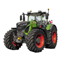
Symbols (A, B) are displayed when the power lift
is lifting or lowering.
● By pressing key (F2) sub-menu EPC rear will
be displayed.
Operation_Pic_number:1
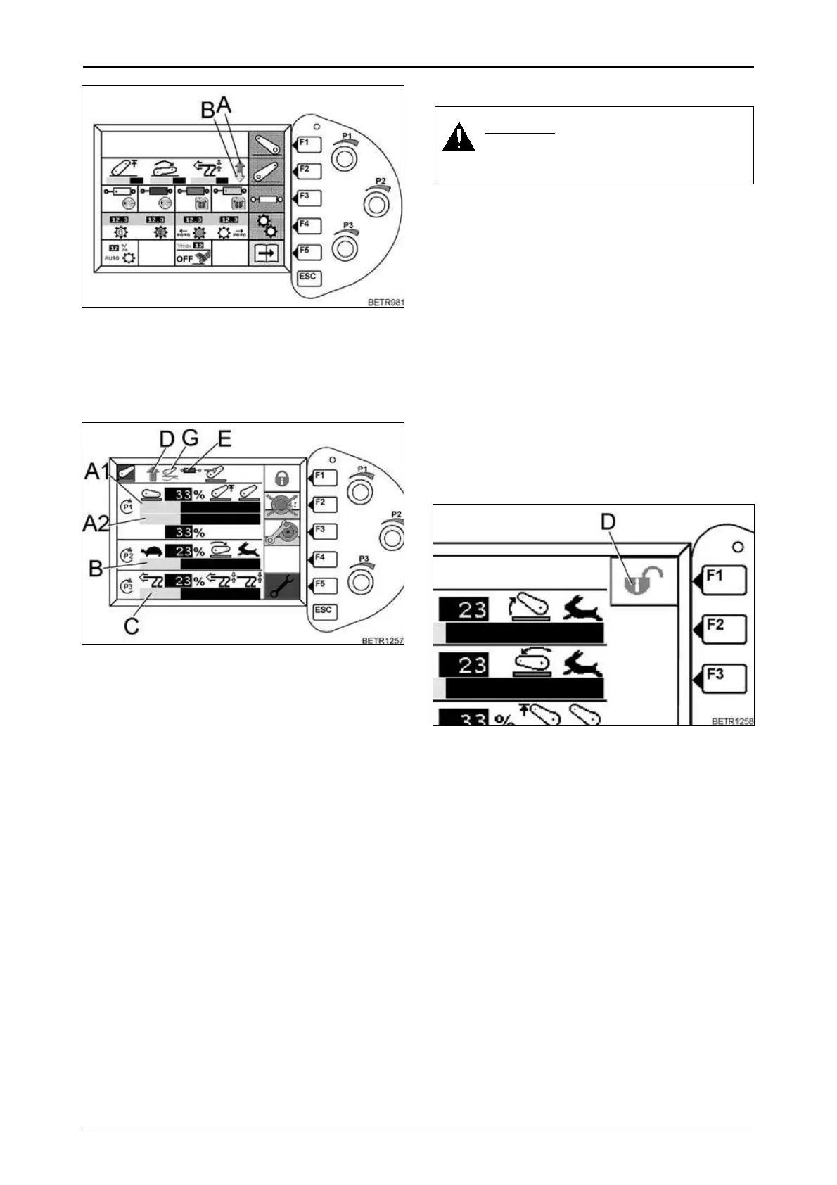
Settings are adjusted by three rotary controls
(P1, P2, P3).
A1 = Lift height limiting
A2 = Position of the power lift
P1 = Rotary control lift height limit/position of
the power lift
B = Lowering speed
P2 = Rotary switch for lowering speed adjust-
ment
C = Position/traction mix control
D = Power lift active
E = Double-acting function active
P3 = Rotary switch, position-traction mix con-
trol
F1 = Power lift lock ON/OFF
F2 = Slip control ON/OFF
F3 = Set slip control
F4 = No function in this sub-menu
F5 = Change engaging speed of shock load
stabilising
G = Floating position
ESC = Return to a higher-level menu
Fig.152
Fig.153
18.2 EPC safety lock
Text-module
When safety lock is active, the power lift does
not function.
ETNum-list
Unlocking the power lift
There are two ways of unlocking the power lift.
Operation_Pic_number:1
1. With the Vario Terminal.
● By pressing key (F1) the lock can be switched
OFF/ON.
Symbol (D) appears.
DANGER:
Select 'Stop' to prevent inadvertent
movements of the power lift.
The safety lock becomes active in any of the
following situations:
1.When the ignition is switched on/off.
2.When starting the tractor.
3.During DA operation of the rear power lift.
4.When there is a fault in the electrical circuit.
5.When rear controls have been operated.
6.By connecting or disconnecting an external
sensor.
Fig.154
 Loading...