3 Mechanical installation
20 Festo – GDCP-CMMS-AS-G2-HW-EN – 1310NH – English
For vertical mounting onto a control cabinet mounting plate:
• Mount the acc ompanying mounting brackets to the
CMMS-AS -...-G2 motor controller.
The two mounting brackets are part of the radiator profile and
transfer heat to the mounting plate.
The motor controllers of the CMMx family are designed in such
a way that they c an be mounted on a heat-dissipating mount-
ing plate if used as intended and installed correctly.
• Use the motor controller exclusively as an installed device
in a control cabinet:
– The mounting position is vert ical with th e po wer supply
lines [X9] leading upwards
– Mount to the mounting brackets with M5 screws.
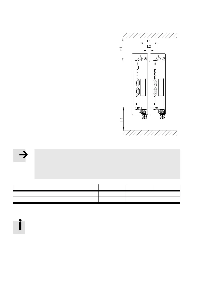
Fig. 3.2 Installation clearance
Note
An exc essive temperature increase results in premature aging or damage to the motor
controller.
• Observe the specified installation clearances to ensure sufficient ventilation
( Tab. 3.2).
Installation clearance
H1
1)
L1 L2
– at an output of 400 W [mm] 100 70 10
– at a rated output of 600 W [mm] 100 140 80
1) Recommendation for optimum wiring of the motor and encoder cable: Installation clearance H1 at the bottom = 150 mm.
Tab. 3.2 Installation c learance
The specified installation clearance L1 = 70 mm relates to an average motor output in
continuous operation (S1 operation ac cording to IEC 60034-1). When subjected to a high-
er output, the c learance L1 = 70 mm is sufficient under the following c onditions:
– The motor is operated at a higher peak load in intermittent operation ( S 3/S 4 opera-
tion according to I EC 60034-1: ac celeration, constant movement with a low load, brak-
ing).
– An excessive temperature increase of the motor c ontroller is prevented by forced
ventilation.
 Loading...


