4 Electrical installation
36 Festo – GDCP-CMMS-AS-G2-HW-EN – 1310NH – English
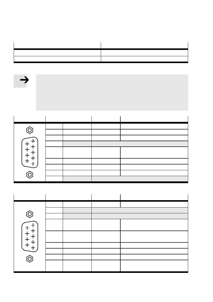
4.7 Serial interface RS23 2/RS485 [X5]
Process valve Version
[X5] on the motor controller D-SUB plug connector, 9-pin, pins
Counterplug D-SUB plug connector, 9-pin, sockets
Tab. 4.16 Connection: RS232/RS485 [X5]
Note
Transmission fault during simultaneous access.
The RS232 and RS485 interfaces can be used to access the controller at the same time
RS485 communication (FCT) is active.
• When communicating via the serial interface only use separate lines that are con-
figured according to the specified pin allocation for RS485 or RS232.
[X5] RS232
Pin Value Description
5
1
2
3
4
6
7
8
9
1 – – –
2 RS232_RxD 10 V, Ri > 2kΩ Receive signal
3 RS232_TxD 10 V, Ra < 2kΩ Transmission signal
4 RS485_A Do not c onnect!
5 GND 0V Reference potential 0 V DC,
not galvanically isolated
6 – – –
7 – – –
8 – – –
9 RS485_B Do not connect!
Tab. 4.17 Pin allocation RS232 [X5]
[X5] RS485
Pin Value Description
5
1
2
3
4
6
7
8
9
1 – –
2 RS232_RxD Do not connect!
3 RS232_TxD Do not connect!
4 RS485_A – Positive transmission and receive
signal
5 GND 0V Reference potential 0 V DC,
not galvanically isolated
6 – – –
7 – – –
8 – – –
9 RS485_B – Negative transmission and receive
signal
Tab. 4.18 Pin allocation RS485 [X5]
 Loading...


