4 Electrical installation
40 Festo – GDCP-CMMS-AS-G2-HW-EN – 1310NH – English
4.9 Power supply [X9]
4.9.1 Protection against electric shock through protective extra-low voltage (PELV):
Warning
Danger of electric shock
• Only use PELV circuits in acc ordance with I EC/EN 60204-1 (protective extra-low
voltage, PE LV) for the electrical power supply.
Also obser ve the general requirements for PE LV circuits as per IEC/EN 60204-1.
• Only use voltage sources which guarantee reliable electrical isolation of the operat-
ing voltage in accordance with I EC/E N 60204-1.
The use of PELV circuits ensures protection from electric shock ( protection from direct and indirect
contact) in ac c ordance with IEC/EN 60204-1 ( Electrical equipment of machines, General requirements).
A 24 V power supply unit used in the system must satisfy the requirements of EN 60204-1 for DC power
supply (behaviour during power interruptions, et c.).
4.9.2 Pin allocation
Process valve
Version
[X9] on the motor controller Phoenix Contact - MSTBA 2.5/7-G-5.08 BK
Counterplug (plug set NEKM-C-4) Phoenix Contact - MSTB 2.5/7-ST-5.08 BK
Tab. 4.21 Connection, power supply
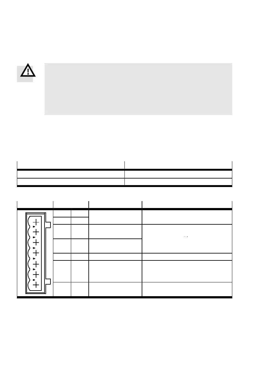
[X9]
Pin Value Description
1
2
3
4
5
6
7
1 L1 single-phase
95 ... 250 V AC
Mains voltage connection for
intermediate c ircuit voltage
2 N
3 ZK + 320 V DC
(max. 400 V DC)
Connection for the external braking
resistor R
BR
› 100 Ω , parallel to the
4 BR-CH 0 V/400 V,
max. 4 A
internal braking resistor,
Not short-circuit proof against L1, N, PE
5 PE PE Mains-side PE c onnection
6 24 V +24 V/1.7 A Supply for the control section, with
DCDC converter, DOUT0 to DOUT3 and
holding brake, max. 1.7 A
7 0V GND Common reference potential for the logic
power supply and control section
Tab. 4.22 Pin allocation: voltage supply [X9]
 Loading...


