4 Electrical installation
24 Festo – GDCP-CMMS-AS-G2-HW-EN – 1310NH – English
4.2. 2 EMC-compliant wiring
Routing cables:
– do not run signal cables parallel to power cables
– the distance between signal cables and power cables should be at least 25 cm
– avoided crossing power cables or running them at a 90° angle.
Screening:
– always run motor and encoder cables so they are screened
– twist unscreened signal cables
– when using screened cables with an unscreened plug housing: the maximum length of
the unscreened wires at the end of the c able is 35 mm.
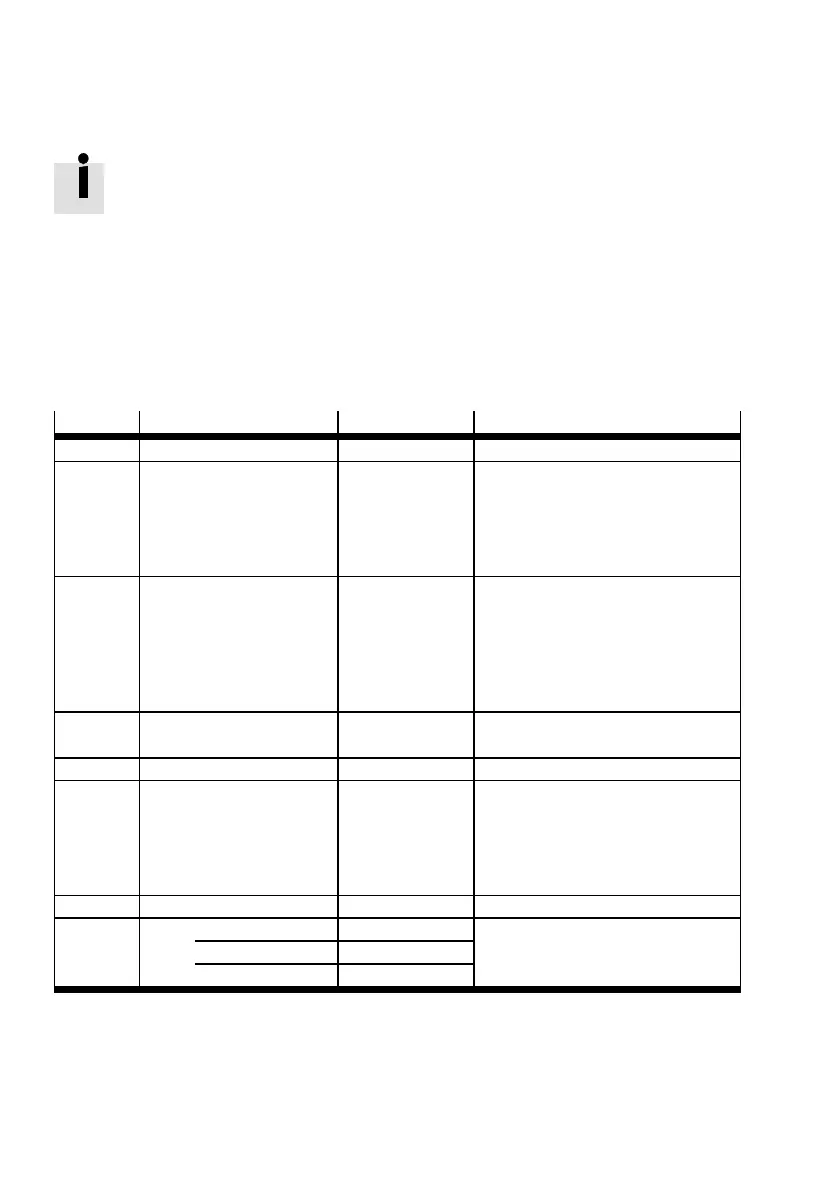
• Observe the permissible cable lengths a nd the required screening for the cables Tab. 4.3 .
Ports
Interface Cable length [m] Screening
[X1] I/O interface ≤ 5 Recommendation: screened
[X2] Encoder ≤ 25 – Screened
– Apply the cable screening of the
encoder cable flat on the plug
housing of the encoder
connection [X2] Chapter 4.4
[X3] STO interface ≤ 30 When wiring outside the c ontrol
cabinet:
– Use screened cable
– Guide screening into the control
cabinet and attach to the side of
the control cabinet.
[X4] CAN ≤ 40
1)
–
[X5] RS232/RS485 ≤ 5 Screened
[X6] Motor ≤ 15
2)
– Screened
– Apply cable screening to the
shield connection terminal of the
corresponding mo tor controller
Chapter 4.8.2
[X9] Power supply ≤ 2 –
[X10] Master/slave: Screened
as input (slave) ≤ 30
as output (master) ≤ 5
1) Cable length is dependent on the bit rate. Specifications relate to 1 Mbit/s.
2) With additional EMC filter: cable length up to 25 m Tab. 4.2.
Tab. 4.3 EMC-compliant wiring
 Loading...


