4 Electrical installation
26 Festo – GDCP-CMMS-AS-G2-HW-EN – 1310NH – English
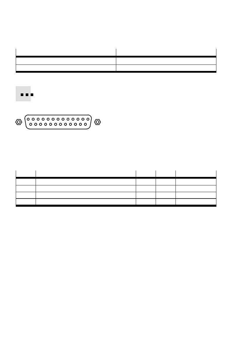
4.3 I/O interface [X1]
Ports Version
[X1] on the motor controller D-SUB plug connector, 25-pin, sockets
Counterplug D-SUB plug connector , 25-pin, pins
Tab. 4.4 Connection I/O interface [ X1]
Available as accessories: screened control cables and D-SUB plug c onnectors
www.festo.com/catalogue.
113
14
25
Fig. 4.1 Connection [X1] on the motor c ontroller
Configuration of the I/O interface:
The I/O interface is configured in positioning mode for the following functions via the digital inputs
DIN9 (=mode bit 1) and DIN12 (=mode bit 0):
Mode
Function DIN 9 DIN 12 Pin allocation
0 Positioning (single record)
1)
0 0 Tab. 4.6
1 Jog/teach 0 1 Tab. 4.7
2 Record linking 1 0 Tab. 4.8
3 Synchronisation 1 1 Tab. 4.9
1) Standard allocation of the I/O interface
Tab. 4.5 Function-dependent configuration o f the digital inputs.
 Loading...


