4 Electrical installation
Festo – GDCP-CMMS-AS-G2-HW-EN – 1310NH – English 31
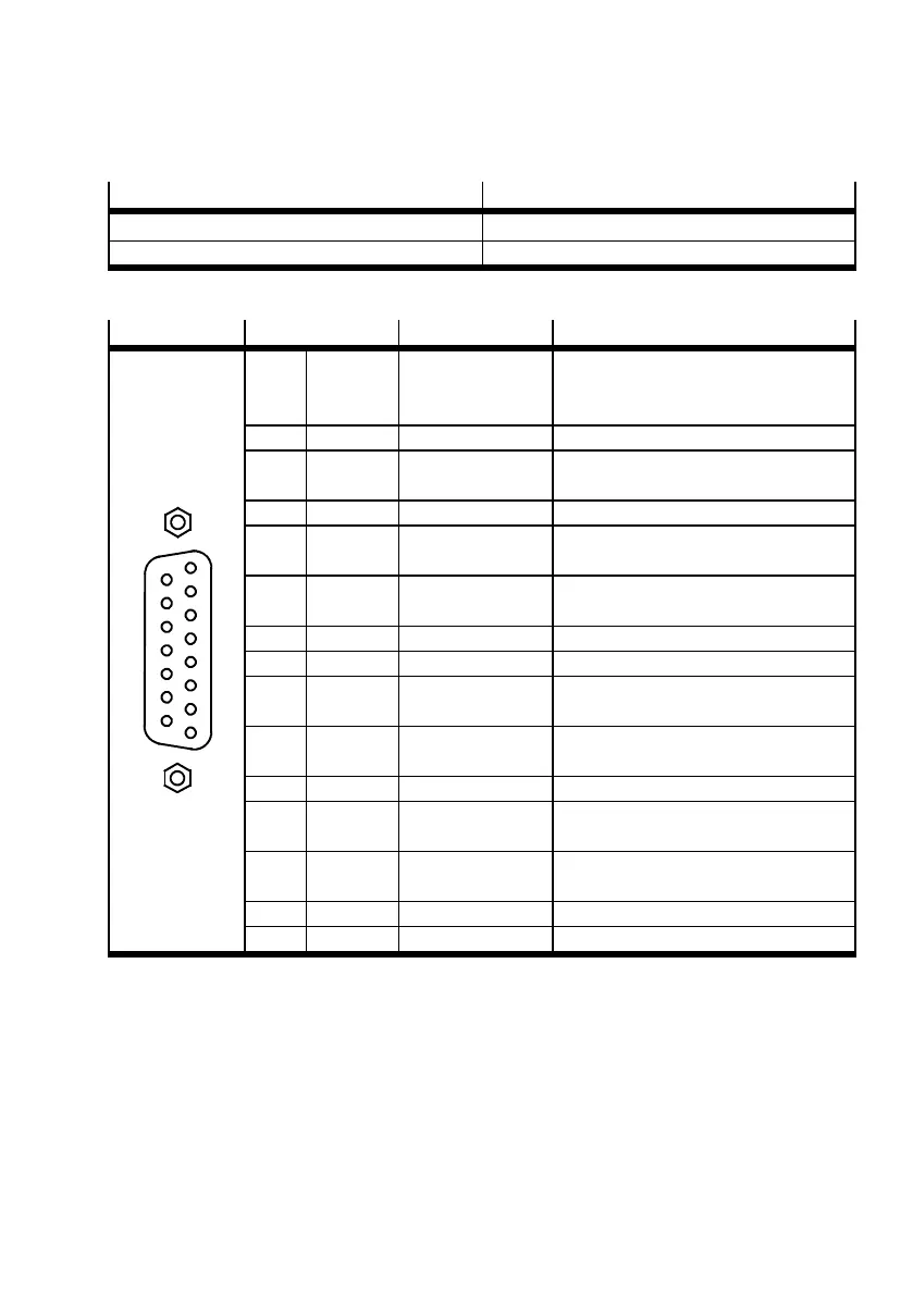
4.4 Encoder [X2]
Process valve Version
[X2] on the motor controller D-SUB plug connector, 15-pin, sockets
Counterplug D-SUB plug connector, 15-pin, pins
Tab. 4.10 Encoder connection
[X2]
Pin Value Description
1
2
3
4
5
6
7
8
9
10
11
12
13
14
15
1 M
T+
+3.3 V / 3 mA Temperature sensor, motor
temperature.
Not occupied with NEBM lines.
2 –U_SENS 0V Connected internally with pin 3
3 GND 0V Reference potential of encoder power
supply and motor temperature sensor
4 – – –
5 #DATA U
pp
=5V
1)
Ri = 120 Ω
2)
RS485 data transmission line
(differential)
6 #SCLK U
pp
=5V
1)
Ri = 120 Ω
2)
Cycle output RS485 (differential) for
data transfer via the EnDat interface
7 – – –
8 – – –
9 +U_SENS 5V(–0%…+5%)
I
max
= 200 mA
Connected internally with pin 10
10 US 5V(–0%…+5%)
I
max
= 200 mA
Operating voltage for EnDat encoder
11 – – –
12 DATA U
pp
=5V
1)
Ri = 120 Ω
2)
RS485 data transmission line
(differential)
13 SCLK U
pp
=5V
1)
Ri = 120 Ω
2)
Cycle output RS485 (differential) for
data transfer via the EnDat interface
14 – – –
15 – – –
1) U
pp
= Peak-to-peak voltage
2) R
i=
Internal resistance
Tab. 4.11 Pin allocation: encoder [X2]
 Loading...


