4 Electrical installation
30 Festo – GDCP-CMMS-AS-G2-HW-EN – 1310NH – English
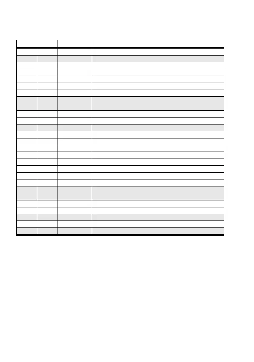
Pin Value Mode = 3 - synchronisation
1 SGN D 0V Screen for analogue signals
2 DIN 12 – Mode bit 0 = “1”
3 DIN 10 – –
4 +VREF +10 V ±4 % Ref erence output for setpoint value potentiometer
5 – – –
6 GND24 – Reference potential for digital inputs and outputs
7 DIN 1 – –
8 DIN 3 24 V
20 kHz (max)
Direction DIR/c ontrol signal CCW
9 DIN 5 – Controller enable (high active)
10 DIN 7 – Limit switch 1
11 DIN 9 Mode bit 1 = “1”
12 DOUT1 24 V 100 mA Output: standstill reached (high active)
13 DOUT3 24 V 100 mA Output:commonerror(lowactive)
1)
14 AGND 0V Reference potential for analogue signals
15 DIN 13 – Stop (low active)
16 DIN 11 – –
17 AMON0 0…10V±4% Output: analogue monitor 0
18 24 V 24 V 100 mA Output 24 V DC, looped through from [X9.6]
19 DIN 0 – –
20 DIN 2 24 V
20 kHz (max)
Pulse CLK/control signal CW
21 DIN 4 – Output stage enable (high active)
22 DIN 6 – Proximity switch 0
23 DIN 8 – Start synchronization
24 DOUT0 24 V 100 mA Output: Controller ready for operation (high active)
25 DOUT2 24 V 100 mA Output: position synchronous (high active)
1) Default setting, configurable in the Festo Configuration Tool (FCT).
Tab. 4.9 Pin allocation: I/O interface [X1], synchronisation
 Loading...


