4 Electrical installation
Festo – GDCP-CMMS-AS-G2-HW-EN – 1310NH – English 35
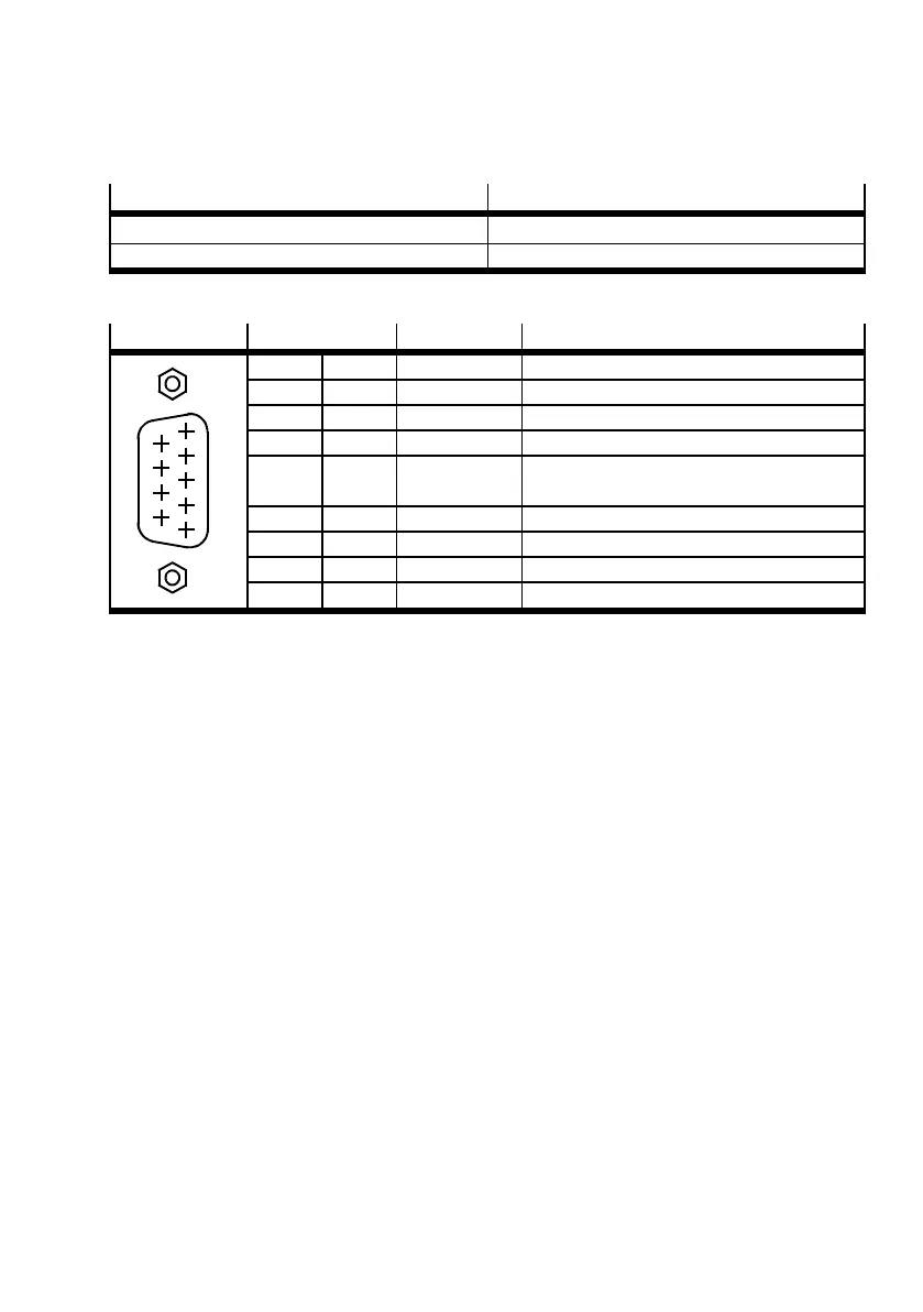
4.6 CAN [X4]
Process valve Version
[X4] on the motor controller D-SUB plug connector, 9-pin, pins
Counterplug D-SUB plug connector, 9-pin, sockets
Tab. 4.14 CAN c onnection
[X4]
Pin Value Description
5
1
2
3
4
6
7
8
9
1 – – –
2 CANL 5V,Ri=60Ω CAN low, signal line
3 GND – CAN GND, not galv anically isolated
4 – – –
5 Screen-
ing
– Connection for the cable screen
6 GND – CAN GND, not galv anically isolated
7 CANH 5V,Ri=60Ω CAN high signal line
8 – – –
9 – – –
Tab. 4.15 Pin allocat ion: CAN [X4]
 Loading...


