A Technical appendix
48 Festo – GDCP-CMMS-AS-G2-HW-EN – 1310NH – English
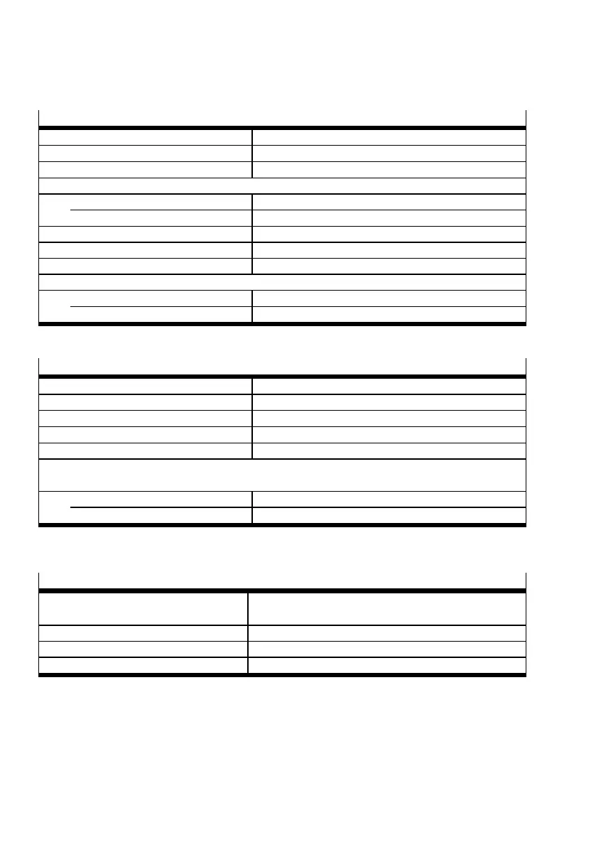
A.2.4 STO interface [X3]
Control port Rel [X3.2]
Nominal voltage [V ] 24 ( related to 0 V)
Voltage range [V] 19.2 … 28.8
Nominal current [mA] 20 (typical; maximum 30)
Voltage threshold
High [V] ≥ 17.9
Low [V] ≤ 2.5
Switching time from high to low [ms] ≤ 12
Switching time from low to high [ms] ≤ 20
Maximum test impulse length [μs] Not specified; no tolerance against test impulses
Service life of relay input, switching cycles [n
op]
CMMS-AS -...-G2 Rev. 01 [n
op]
100 000
CMMS-AS -...-G2 Rev. 02 [n
op]
10 x 10
6
Tab. A.6 Connection data: Control port Rel [X3]
Acknowledgment contact NC1, NC2 [X3.5, X3.6]
Feature Relay contact, normally closed
Max. voltage [V DC] < 30
Nominal current [mA] < 2000 at 30 V
Switching time closing [ms] < (Switching time from high to low
1)
+ 9 ms)
Switching time opening [ms] < (Switching time from low to high
1)
+ 9 ms)
Service life of acknowledgment contact, switching cycle n
op
(at 24 V and I
Contact
=10mA;theservice
life is reduced with higher load currents)
CMMS-AS -...-G2 Rev. 01 [n
op]
100 000
CMMS-AS -...-G2 Rev. 02 [n
op]
10 x 10
6
1) Switching time Tab. A.6
Tab. A.7 Connection data: Acknowledgment contact NC1/NC2 [X3]
Auxiliarysupply24V,0V–output[X3.1,X3.3]
Feature Logic supply voltage routed out of the motor controller
(fed in at [X9], not additionally filtered or stabilised).
Nominal voltage [V] 24
Nominal current [mA] 100 (not short-circuit proof )
Voltage drop [V ] ≤ 1 (for nominal current)
Tab. A.8 Connection data: Auxiliary supply output [X3]
 Loading...


