2 Product Overview
Festo – GDCP-CMMS-AS-G2-HW-EN – 1310NH – English 15
2.4 Display and control elements
2.4.1 Seven-segment display
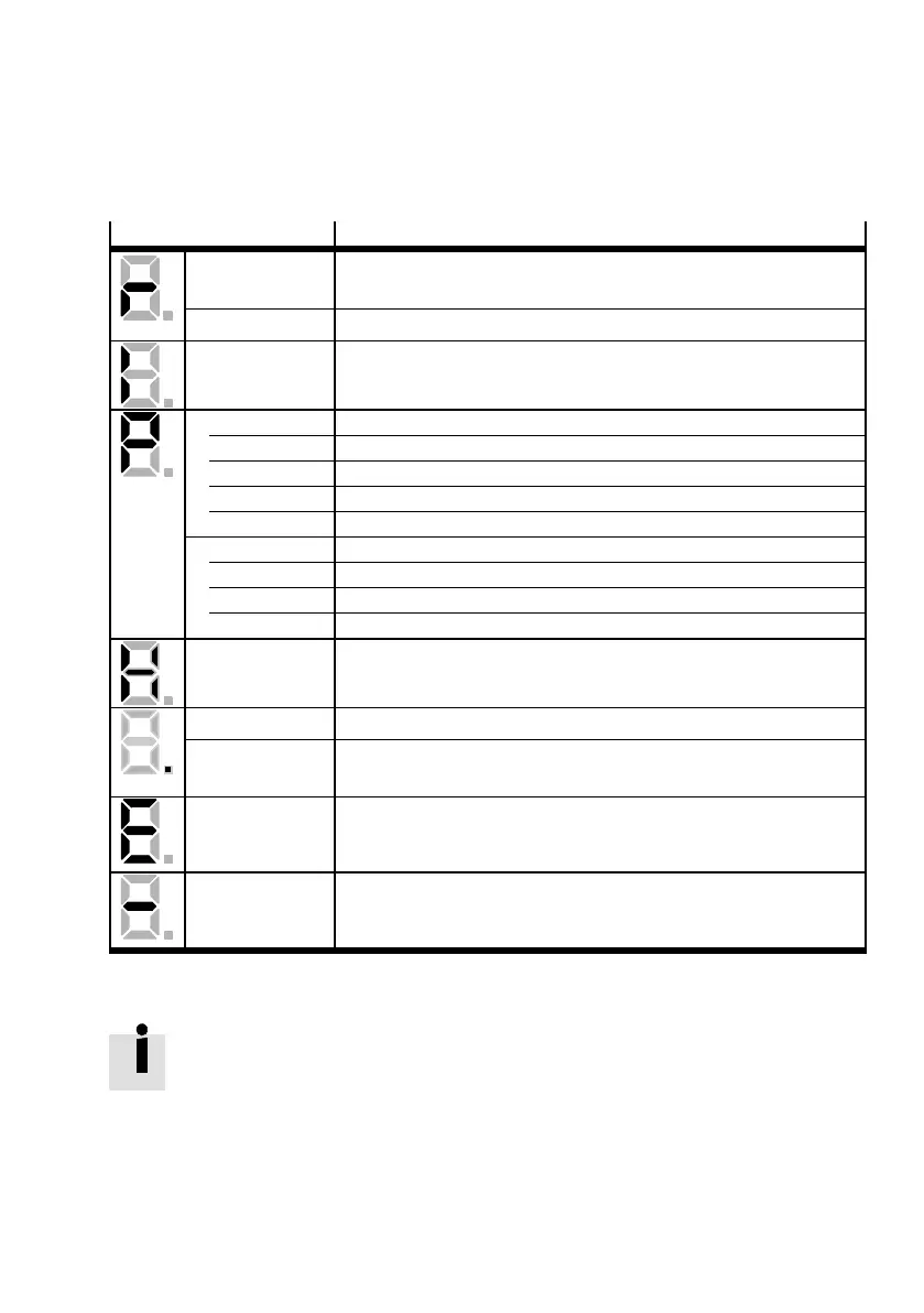
Display
1)
Meaning
Rotating outside
segments
Speed mode (speed adjustment):
Display changes corresponding to ro tor position and speed.
Middle segment Controller enable active (motor is energised).
I Force mode (current control)
Pxxx Positioning mode, record number x x x
000 – No positioning record active
001...063 – Positioning record 001 ... 063 active
070/071 – Jogging+/jogging–
064 – Manual travel via FCT or FHPP direct record (direct operation)
PHx Homing phase x
0 – Searching travel to the primary destination (limit switch or stop)
1 – Creep to the reference point
2 – Move to the axis zero point
H Two-channel safety function requested ( DIN4 [ X1.21] and Rel [X3.2])
Dot Start program (Bootloader) active
Flashing point – Firmware file (memory card) is being read
– Display of errors th rough the start programme
Exxy Error (E = error)
Number: two-position main index (x x), single-position subindex (y)
Example: E 0 1 0 Appendix B.
–xxy– Warning
Number: two-position main index (x x), single-position subindex (y).
Example:-170- Appendix B.
1) Several characters are displayed one after the other.
Tab. 2.2 Seven-segment operation and error display ( Fig. 2.2 2 )
Warnings are automatically acknowledged when the c ause is no longer present. Error
messages are ac knowledged via:
– the parameterisation software FCT
– the fieldbus (control word)
– or a decreasing edge at [X1] DIN5.
 Loading...


