4 Electrical installation
Festo – GDCP-CMMS-AS-G2-HW-EN – 1310NH – English 33
4.5 STO interface [X3]
4.5.1 Pin allocation
Process valve
Version
[X3] on the motor controller Phoenix Contact - MC 1.5/6-GF-3.81 BK
Counterplug (plug set NEKM-C-4) Phoenix Contact - MC 1.5/6-STF-3.81 BK
Tab. 4.12 Connection: STO interface [X3]
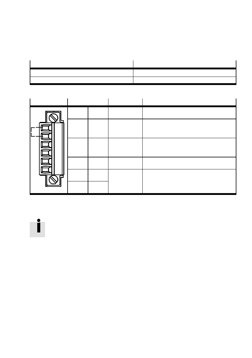
[X3]
Pin Value Description
1
2
3
4
5
6
1 24 V 24 V DC 24 V DC supply carried out
2 REL 0 V/24 V DC Setting and resetting the relay for
interrupting the driver supply
3 0V 0V
(GN D 24 V DC)
Reference potential for the PLC
(Re ference potential for the 24 V DC supply)
4 – – –
5 NC1 Max. 25 V AC,
30 V DC, 2 A
Potential-free feedback contact for driver
supply, NC contact
6 NC2
Tab. 4.13 Pin allocation: Interface [X3] (Circuitry without use of the STO safety function)
4.5.2 Circuitry without use of the STO safety function [X3]
If you do not need the integrated STO safety function in your application, you must bridge
Pin 1 and Pin 2 at the X3 interface to operate the motor c ontroller Tab. 4.13.
This deactivates the integrated safety function!
When using this circuitry for the CMMS-AS-...-G2, safety in the application must be
ensured through other appropriate measures.
 Loading...


