4 Electrical installation
Festo – GDCP-CMMS-AS-G2-HW-EN – 1310NH – English 37
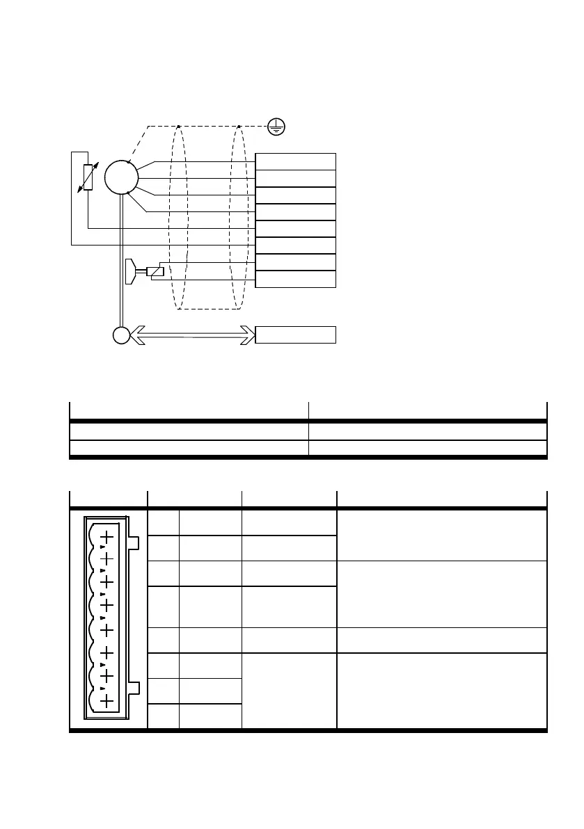
4.8 Motor [X6]
U
V
W
PE
M
T+
M
T–
BR+
BR–
E
M
3~
T
[X6]
[X2]
Fig. 4.2 Connection to the motor
4.8.1 Pin allocation
Process valve
Version
[X6] on the motor controller Phoenix Contact - MSTBA 2.5/8-G-5.08 BK
Counterplug (plug set NEKM-C-4) Phoenix Contact - MSTB 2.5/8-ST-5.08 BK
Tab. 4.19 Motor connection
[X6]
Pin Value Description
1
2
3
4
5
6
7
8
1 BR– 0V For motors E MMS-AS -…- TSB/TMB: holding
brake (motor)
2 BR+ 24 V
3 M
T–
0V – Temperature sensor
1)
– Optional N/C contact, N/O contact, PTC
or KTY
– For EMMS-AS motors: PTC
4 M
T+
+3.3V
5mA
5 PE – PE connection of the motor cable
6 W Chapter A.2.7 Connection of the three motor phases
7 V
8 U
1) In the motor and connecting cable, reliable separation of the motor temperature sensor from the motor circuit m ust be ensured.
Tab. 4.20 Pin allocation: Motor [X6]
 Loading...


