4 Electrical installation
42 Festo – GDCP-CMMS-AS-G2-HW-EN – 1310NH – English
4.10 Master/slave interface [X10]
The master/slave interface is bi-directional and can be configured with the FCT software as an input or
as an output for master/slave operation:
– Master ( incremental encoder emulation): Output of tracking signals A/B/N of an incremental en-
coder for ac tuating a slave c ontroller
– Slave (synchronisation): Input fo r tracking signals A/B, pulse/direction signals CLK/DIR or forward/
backward signals CW/CCW for synchronisation with a master controller .
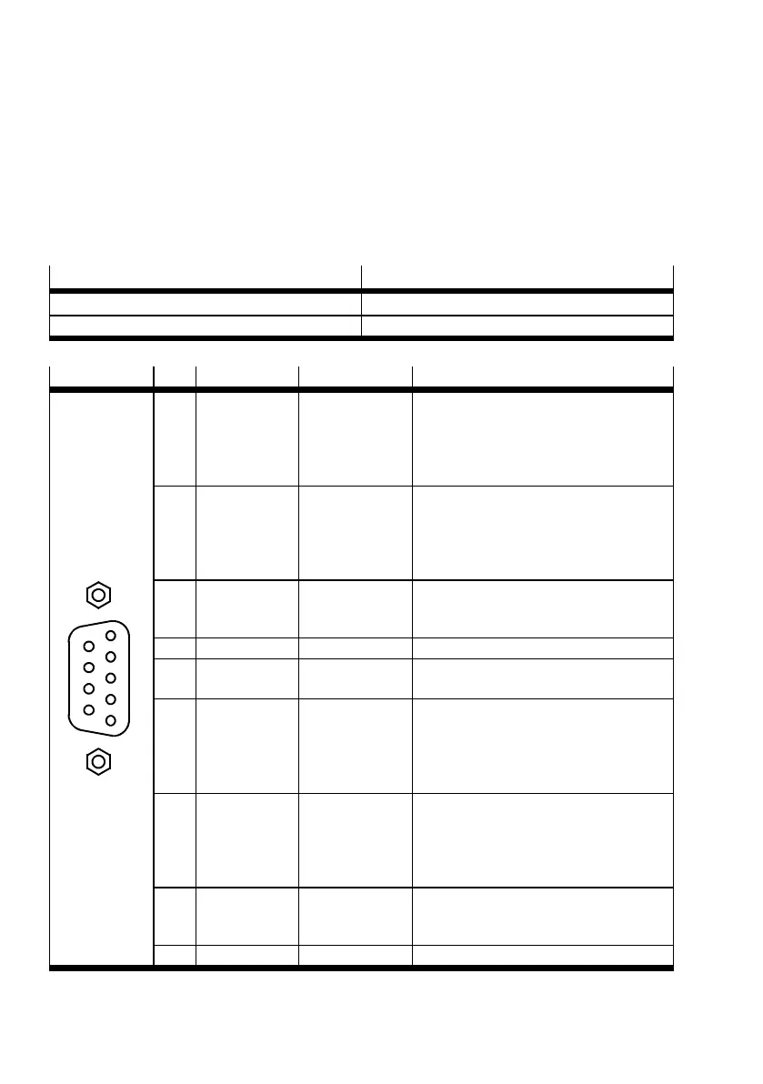
Process valve
Version
[X10] on the motor controller D-SUB plug connector, 9-pin, sockets
Counterplug D-SUB plug connector, 9-pin, pins
Tab. 4.23 Connection of master/slave interface
[X10]
Pin Designation Value Description
6
7
8
9
2
1
3
4
5
1 A
CLK
CW
5VDC
Ri = 120 Ω
max. 150 kHz
– Tracking signal A
– Pulse CLK
– Pulses cloc kwise CW
– Positive polarity in accordance with
RS422
2 B
DIR
CCW
5V
Ri = 120 Ω
max. 150 kHz
– Tracking signal B
–DirectionDIR
– Pulses counterclockwise CCW
– Positive polarity in accordance with
RS422
3 N 5V
Ri = 120 Ω
max. 150 kHz
– Incremental enco der zero pulse N
– Positive polarity in accordance with
RS422
4 GND
1)
– Reference GND for incremental encoder
5 VCC +5 V ±5 %,
100 mA
Auxiliary supply, max. load 100 mA,
short-circuit proof
6 #A
#CLK
#CW
5V
Ri = 120 Ω
max. 150 kHz
– Tracking signal A
– Pulse CLK
– Pulses cloc kwise CW
– Negative polarity in acc ordance with
RS422
7 #B
#DIR
#CCW
5V
Ri = 120 Ω
max. 150 kHz
– Tracking signal B
–DirectionDIR
– Pulses counterclockwise CCW
– Negative polarity in acc ordance with
RS422
8 #n 5V
Ri = 120 Ω
max. 150 kHz
– Zero pulse N
– Negative polarity in acc ordance with
RS422
9 GND
1)
– Screening for the connecting cable
1) Pin 4 and pin 9 are connected internally
Tab. 4.24 Pin allocation: Master/slave interface [ X10]
 Loading...


