34 MS-9050 Series Manual — P/N 52413:F 10/22/2010
Installation Optional Modules/Accessories Installation
Before installing the module, place the disconnect switch to the right (disconnect) position to pre-
vent accidental activation of the municipal box. Note that a Disconnect LED will illuminate after
the module is installed in the MS-9050UD. In addition, the System Trouble LED will turn on to
indicate the Disconnect condition.
The following steps must be followed when installing the 4XTMF module:
1. Remove all power (Primary and Secondary) from the FACP before installing 4XTMF.
2. Cut jumper JP28 on the main circuit board to allow the control panel to supervise the 4XTMF
module.
3. Remove two screws securing main circuit board to mounting plate and install two standoffs for
securing 4XTMF module to main circuit board. Refer to Figure 2.11 for standoff locations on
main circuit board.
4. Carefully plug the connectors on the 4XTMF module into connectors J8 and J9 on the MS-
9050UD main circuit board, being careful not to bend any pins.
5. Secure 4XTMF module to standoffs with supplied screws removed in step 3.
6. Reapply power to the FACP.
7. For proper 4XTMF operation, the main circuit board output relays must be programmed for
the factory default settings: Alarm Relay 1, Trouble Relay 2, and Supervisory Relay 3.
8. When the installation has been completed, enable the 4XTMF module by sliding the
disconnect switch to the left.
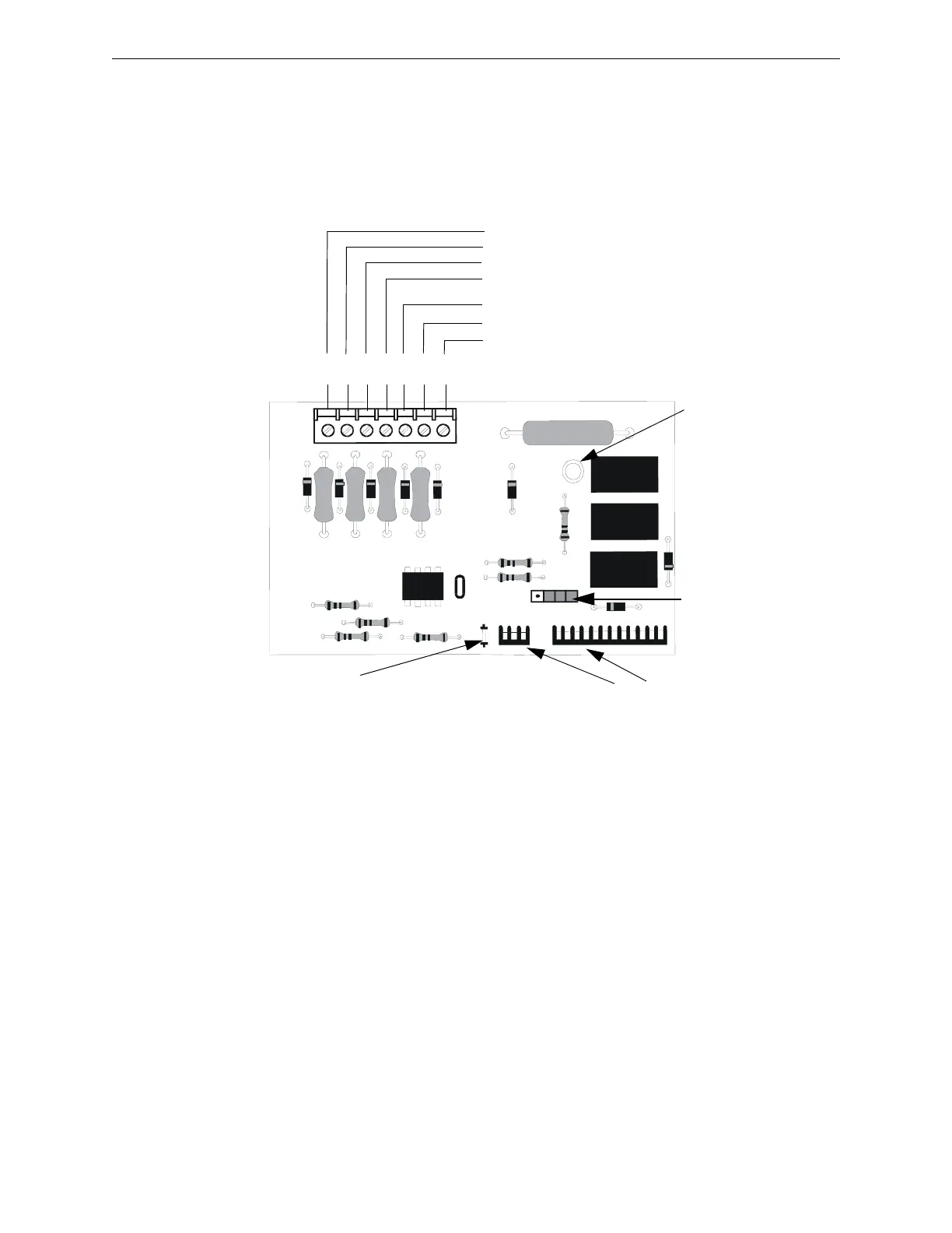
Figure 2.10 4XTMF Transmitter Module
Connect to FACP at J8 & J9
Disconnect Switch
shown in disconnect
position
TBL Jumper
}Remote Alarm (power-limited)*
}Remote Trouble (power-limited)*
No connection
}Municipal Box (nonpower-limited)*
1 2 3 4 5 6 7
+ - + - + -
Polarities are shown for module activation
Note: 4XTMF Module is not directly suitable for transmitting reverse polarity supervisory signal. For an
application using reverse polarity of a supervisory signal, refer to “FACP with Keltron” on page 198.
* Wiring from these
terminals can exit the
protected premises.
Dummy load terminals 6
and 7 (4.7K, ¼ watt
resistor) if Municipal Box
is not connected.
Disconnect LED
4xtmfl.wmf