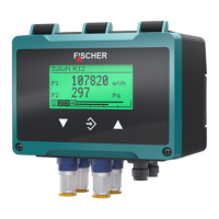
The device described is the FISCHER DE90 PRO-LINE® Differential Pressure Transmitter, designed for measuring overpressure, under-pressure, and differential pressure in neutral gaseous media. It is available in 1-channel and 2-channel versions, with some models also supporting a 3-channel "virtual" measurement derived from the first two.
Function Description:
The DE90 operates based on a piezo-resistive sensor element. This element utilizes a silicon diaphragm equipped with a measuring bridge. When a pressure difference occurs, the diaphragm deflects, causing a change in the resistance of the measuring bridge. This change is then evaluated by the integrated electronics and converted into a display, switching contacts, and an output signal. The output signal can be damped, spread, inverted, or non-linearly transformed via a table function.
The device can be equipped with two digital interfaces:
- USB OTG: All devices include a USB interface for firmware updates and importing/exporting parameters using a USB stick or by connecting to a computer with the "inTouch" PC software.
- RS485 Modbus RTU: Optionally, the device can be equipped with a Modbus interface. In this configuration, the analog and switching outputs are not available, and measured values are interrogated by a Modbus master. The DE90 typically functions as a slave in a Modbus RTU network, supporting up to 247 devices in a single line network. Star-shaped networks are not allowed.
Important Technical Specifications:
- Type Designation: DE90
- Pressure Type: Differential pressure
- Measurement Principle: Piezo-resistive
- Reference Conditions (acc. to IEC 61298-1):
- Temperature: +15 … +25 °C
- Relative humidity: 45 … 75 %
- Air pressure: 86 … 106 kPa (860 … 1060 mbar)
- Installation position: Vertical
- Input Variables (Asymmetric Measuring Ranges):
- Ranges from 0…25 Pa up to 0…250 mbar (0…25 kPa)
- Overload pressure: 750 mbar to 2.5 bar
- Bursting pressure: 1 bar to 5 bar
- Sensor types A and B, with some ranges offering higher overload/bursting pressure capability.
- Input Variables (Symmetric Measuring Ranges):
- Ranges from -25…+25 Pa up to -250…+250 mbar (-25…+25 kPa)
- Overload pressure: 750 mbar to 2.5 bar
- Bursting pressure: 1 bar to 5 bar
- Sensor types A and B, with some ranges offering higher overload/bursting pressure capability.
- Analog Outputs:
- 1-channel version: 1 analog output
- 2-channel version: 2 analog outputs
- Output signals: 0…20 mA, 4…20 mA, 0…10 V, 2…10 V, 1…5 V
- Signal range: 0.0…21.5 mA, 0.0…10.5 V
- Load RL: ≤ 600 Ω (current), ≥ 2 kΩ (voltage)
- Turn down: 4:1
- Switching Outputs:
- 1-channel version: 2 switching outputs
- 2-channel version: 4 switching outputs
- Type: Potential-free semiconductor switch (MOS-FET)
- Programmable switching function: Single pole make contact (NO), Single pole break contact (NC)
- Max. switching voltage: 3…32 V AC/DC
- Max. switching current: 0.25 A
- Max. switching capacity: 8 W / 8 VA, RON ≤ 4 Ω
- Digital Interfaces:
- USB: USB On The Go 2.0, Data rate 12 Mbit/s (Full Speed), Micro USB type B port, Host/Device mode communication.
- Modbus RTU: RS 485 interface, Modbus RTU report, Application Protocol Specification V1.1b3 (April 26, 2012), Address 1…255, Baud rate 2400…115200 Baud, Parity (Even, uneven, parity), Stopbits 1…2.
- Auxiliary Energy:
- Nominal voltage: 24 V AC/DC
- Admissible operating voltage Ub: 19.2…28.8 V AC/DC
- Power consumption: Type 2W (VA), Max. 3W (VA)
- Operating Conditions:
- Ambient/Medium/Storage temperature range: -20…+70 °C (Standard), -20…+60 °C (ATEX)
- Protection: IP65
- Display: Full graphic LC display, Resolution 128 x 64 Pixel, RGB backlight, 6 digits for measured value display.
- Construction Design:
- Dimensions (without connections): 120 x 81.5 x 95 mm
- Weight: max. 380 g
- Materials in contact with medium: Silicon, PVC, FKM, aluminium, brass, stainless steel
- Materials in contact with surroundings: Polyester, PET, polyamide 6.6, aluminium, nickel-plated brass, stainless steel
Usage Features:
- Installation: Designed for mounting on assembly plates or flat walls, supplied with a pre-mounted 35 mm plastic mounting rail. Can also be mounted on a 35mm hat rail. Calibrated for vertical installation but can be used in any position with offset correction.
- Process Connection: Various connection types are available, including pneumatic plug connections for hydraulic hoses, CK quick-action screw connections for soft hoses, and cutting ring screw connections for hydraulic tubes (stainless steel). Pressure lines should be short, installed with inclination to avoid water pockets, and protected from pressure surges.
- Electrical Connection: Two M12 flange connectors are used. For explosion-proof models, local regulations and guidelines for electrical systems in explosive areas must be observed. A CE-conform mains adapter with a slow 200 mA fuse is required for power supply. The outer ground connection must always be connected to protective potential equalization.
- Start-up: After successful installation control, the device displays a start screen and then switches to the measured value display.
- Measured Value Display: Different presentation variants are available, including 1-channel, 2-channel, and 3-channel (virtual) displays. The display can show individual or simultaneous channels and includes a bargraph.
- Backlighting: RGB backlighting allows for various colored backgrounds and can be configured to change color when limits are overstepped, signaling different operating states (e.g., normal, warning, danger).
- Keyboard: Three buttons (Page down, Call up/Save, Page up/Increase) are used for navigation and input. Functions include text input, value input (with automatic limit checks and number overflow handling), and option selection.
- Configuration: Parameters can be quickly modified via a "Quick access" menu (language, measuring point designation, unit, measuring range, damping). More comprehensive changes can be made using the "inTouch" PC software via the USB interface. Configuration can also be done directly via the keyboard in the configuration menu.
- Login System: Users can log in/out with passwords to access configuration settings. Different user levels (User 1, 2, 3, Administrator) have varying permissions (view, edit, firmware update, manage users).
- Measurement Modes: Supports various modes for measurement channels, including Linear, Flow rate, Table, and Volume flow, each with specific parameterization for characteristic curves. For the 3-channel version, "Difference" and "Dynamic filter monitoring" modes are available.
- Damping: A damping parameter can be set to stabilize unsteady measurement readings.
- Offset: An offset can be applied to correct the zero-point signal.
- Zero-point Window: Defines a range around zero where the display value is set to zero, preventing unsteady readings at idle.
- Signal Limits: Output signals can be limited to prevent error messages in downstream systems.
- Modbus RTU Settings: Baud rate, data format (data, parity, stop-bit), Modbus address, and byte order can be configured.
Maintenance Features:
- Maintenance-free: The device is generally maintenance-free.
- Regular Inspection: Recommended regular inspections include checking function with downstream components, leak-tightness of pressure lines, and electrical connections.
- Cleaning: For ATEX devices, regular cleaning with a damp cloth is necessary to prevent heat build-up, with intervals depending on local dust.
- Service: Defective or faulty devices should be sent to the repair department, coordinating shipments with the sales department.
- Process Media Residues: Before returning devices, ensure they are thoroughly cleaned to remove any hazardous process media residues.
- Transport: The device should be protected against impacts and transported in original packaging or a suitable container.
- Disposal: Dispose of the device and packaging materials in compliance with national waste and recycling guidelines.