FISCHER Mess- und Regeltechnik GmbH Operation | 5
BA_EN_DE90 43
5.5 Configuration
With the inTouch® software, parameterization can also be carried out on the
PC. The finished parameter set is then transferred to the DE90 via the USB in-
terface.
WARNING
Parameterization in hazardous areas
The housing must not be opened within the ATEX area. Therefore parameteriz-
ation and firmware update via the USB interface may only be carried out outside
the hazardous area.
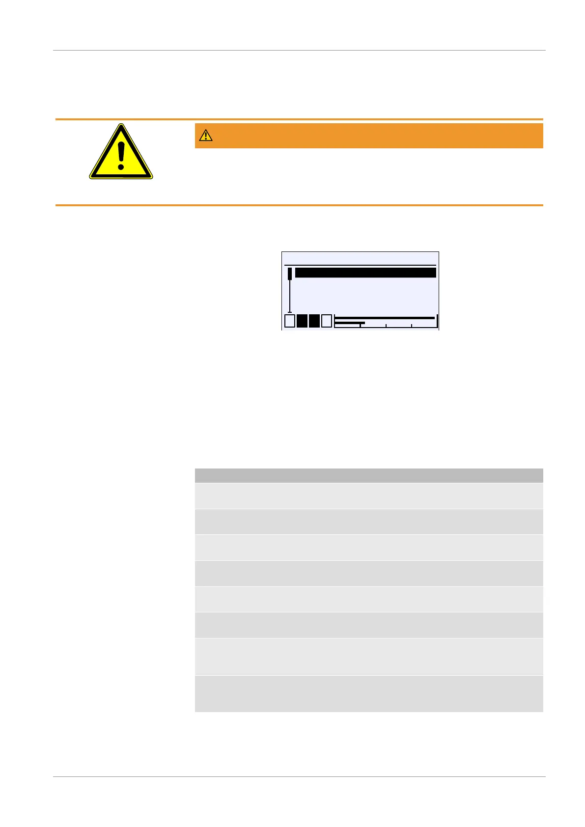
Directory: \Configuration
Level: 1
\Configuration
1 2 3 4
Channel 1
Channel 2
Channel 3
Analog output
A
A
U
A
A
Fig.54: Configuration
NOTICE!The device has 1 or 2 measuring channels, depending on the
version. For a device with only one measuring channel, the menus for the
second channel are hidden.
The parameters and menus are described for a device with two channels. The
displays and descriptions shown may therefore differ for a device with only one
channel.
Only devices with two channels have a third channel. This channel is a so-
called 'virtual' channel whose display values are calculated by a mathematical
function from the two measurement channels 1 and 2.
Menu name Description
Channel 1 A With this menu the 1st measuring
channel is parameterized.
Channel 2 A With this menu the 2nd measuring
channel is parameterized.
Channel 3 A With this menu the 3rd measuring
channel is parameterized.
Analog output A This menu is used to parameterize the
analog outputs..
Switch output A This menu is used to parameterize the
switching outputs.
Display A This menu is used to parameterize the
display.
Modbus RTU A This menu is only available for Modbus
devices and is used to configure the in-
terface.
Back E This represents the output (Exit) of the
parameterization menu. This takes you
'Back' to the main menu.