5 | Operation FISCHER Mess- und Regeltechnik GmbH
78 BA_EN_DE90
5.5.4 Analog output
Directory: \Configuration\Analog output
Level: 2
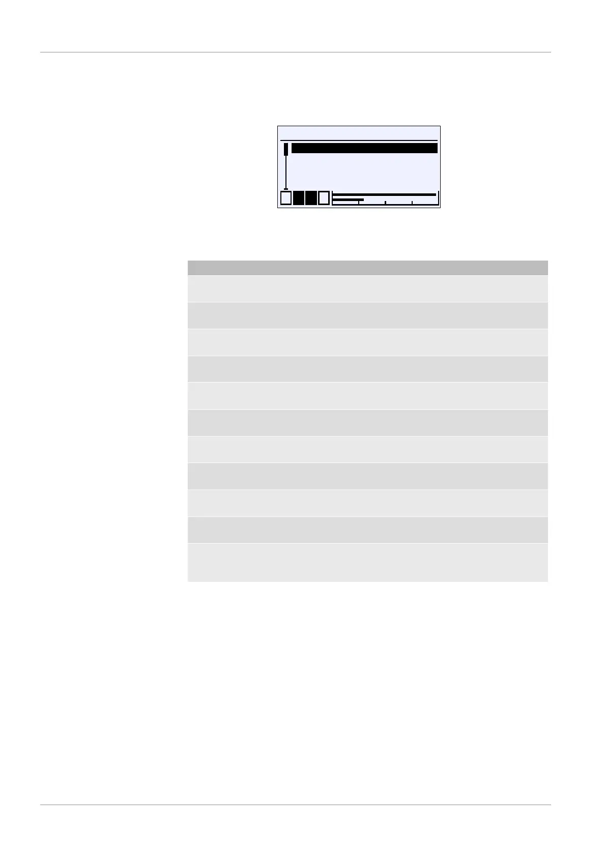
\...\Analog output
1 2 3 4
An.output 1 type
An.output 1 assignmnt
An.output 2 type
An.output 2 assignmnt
A
A
U
A
A
Fig.112: Analog output
NOTICE!In devices with just one measuring channel, the parameters for
the second output are not required.
Menu name Description
An.output 1 type A This menu is used to define the output
signal for output 1.
An.output 1 assignmt A The measuring channel of output 1 is
assigned in this menu.
Output 2 type A This menu is used to define the output
signal for output 2.
An.output 2 assignmt A The measuring channel of output 2 is
assigned in this menu.
Limit I min. Parameters for the lower limit of the
current output.
Limit I max Parameters for the upper limit of the
current output.
I-error signal Parameters for the error signal of the
current output.
Limit U min. Parameters for the lower limit of the
voltage output.
Limit U max. Parameters for the upper limit of the
voltage output.
U error signal Parameters for the error signal of the
voltage output.
Back E This represents the output (exit) of the
menu. Press 'back' to return to the con-
figuration menu.
The parameters for the type and assignment work for both channels identically.
Therefore, the parameters for channel 1 are explained as an example.
The same also applies for limit parameters that are explained for the current
signal. If the signal type is changed, the parameters that need to be entered for
the previous signal are retained.