FISCHER Mess- und Regeltechnik GmbH Assembly | 3
BA_EN_DE90 19
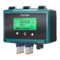
3.4.3.2 Auxiliary energy supply
The following illustrations explain the principle of the power supply of the DE90
in the Modbus network. However the feeder nodes are not part of the delivery
scope and need to be installed by the operator himself.
BUS-D1
BUS-D0
BUS-R
AC/DC
AC
BUS-D1
BUS-D0
BUS-R
U
b
+
U
b
-
1
3
2
4
5
DE90
Master
+
Auxiliary energy
Feed
1
3
2
4
5
1
3
2
4
5
ST1 ST2
1
3
2
4
5
A
max. 2A
(~)
(~)
Fig.20: Main supply
Please note that the M12 plugs are approved for max. 2A. This value may
already be exceeded if there are more than 12 devices of type DE90. In this
case, an intermediate auxiliary energy feed should be provided at a suitable
place.
AC/DC
AC
BUS-D1
BUS-D0
BUS-R
U
b2
+
U
b2
-
1
3
2
4
5
DE90
Auxiliary energy 2
Feed
1
3
2
4
5
1
3
2
4
5
ST1 ST2
DE90
1
3
2
4
5
1
3
2
4
5
ST1 ST2
BUS-D1
BUS-D0
BUS-R
2
4
5
1
3
A
max. 2A
(~)
(~)
U
b
+
U
b
-
(~)
(~)
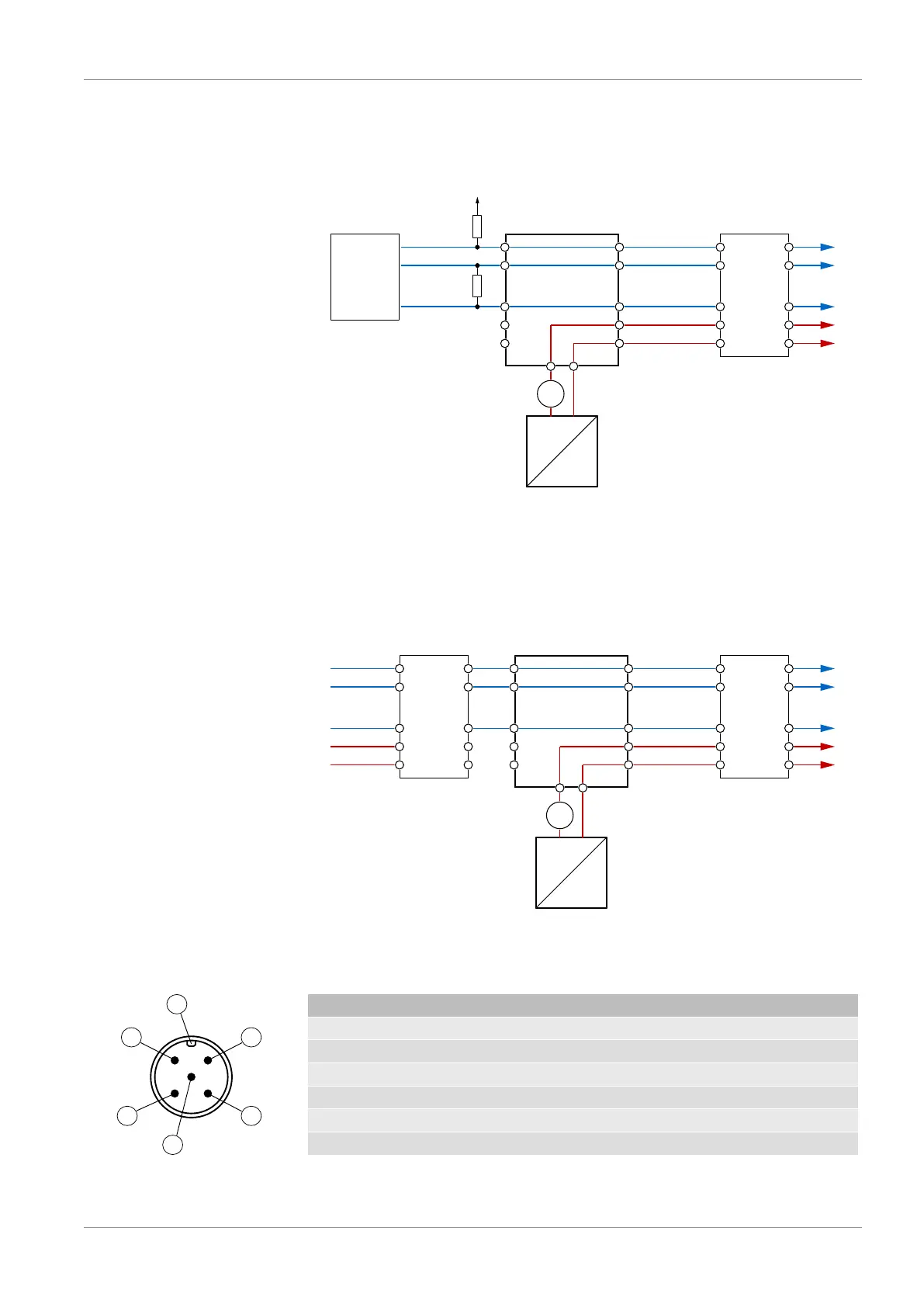
Fig.21: Intermediate supply
3.4.3.3 M12 plug 1: Modbus IN
Fig.22: M12 plug 5-pin
PIN Signal Cable colour
1 Operating voltage +U
b
Brown
2 Modbus BUS-D1 White
3 Operating voltage - U
b
Blue
4 Modbus BUS-D0 Black
5 Modbus BUS-R Grey
A Coding