FISCHER Mess- und Regeltechnik GmbH Operation | 5
BA_EN_DE90 81
5.5.5 Switch output
Directory: \Configuration\Switch output
Level: 2
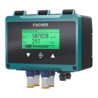
\...\Switch output
1 2 3 4
SP1 assignment
SP1 on
SP1 off
SP1 delay on
A
U
Fig.116: Switch output
NOTICE!Depending on the model, the device has 2 or 4 switch outputs.
As the configuration for each switch output is the same, only the paramet-
ers for the first switch output are shown.
Menu name Description
SP1 assignment A This menu assigns the switch output 1
to channel or switches it off.
SP1 on The activation point is set with this
parameter.
SP1 off The deactivation point is defined with
this parameter.
SP1 delay on The activation delay is defined with this
parameter.
SP1 delay off The deactivation delay is defined with
this parameter.
SP1 function A The contact point is defined with this
menu.
Back E This represents the output (exit) of the
menu. Press 'back' to return to the con-
figuration menu.
5.5.5.1 SP1 assignment
Directory: \Configuration\Switch output\SP1 assignment
Level: 3
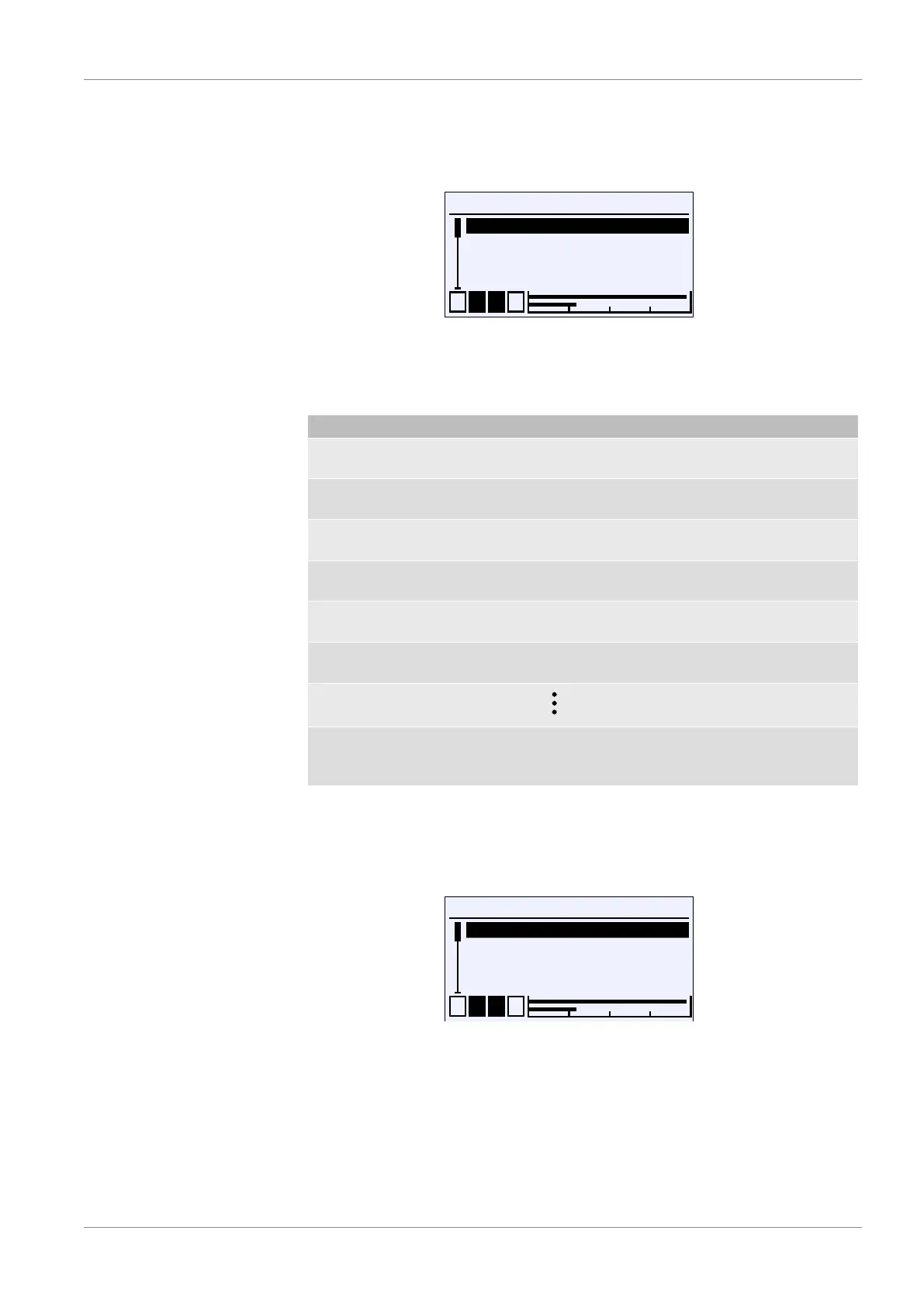
\...\...\SP1 assignment
1 2 3 4
Inactive
Channel 1
S
U
R
RChannel 2
Channel 3 R
Fig.117: SP1 assignment
This menu can be used to assign or deactivate the switch point of a channel.