3 | Assembly FISCHER Mess- und Regeltechnik GmbH
18 BA_EN_DE90
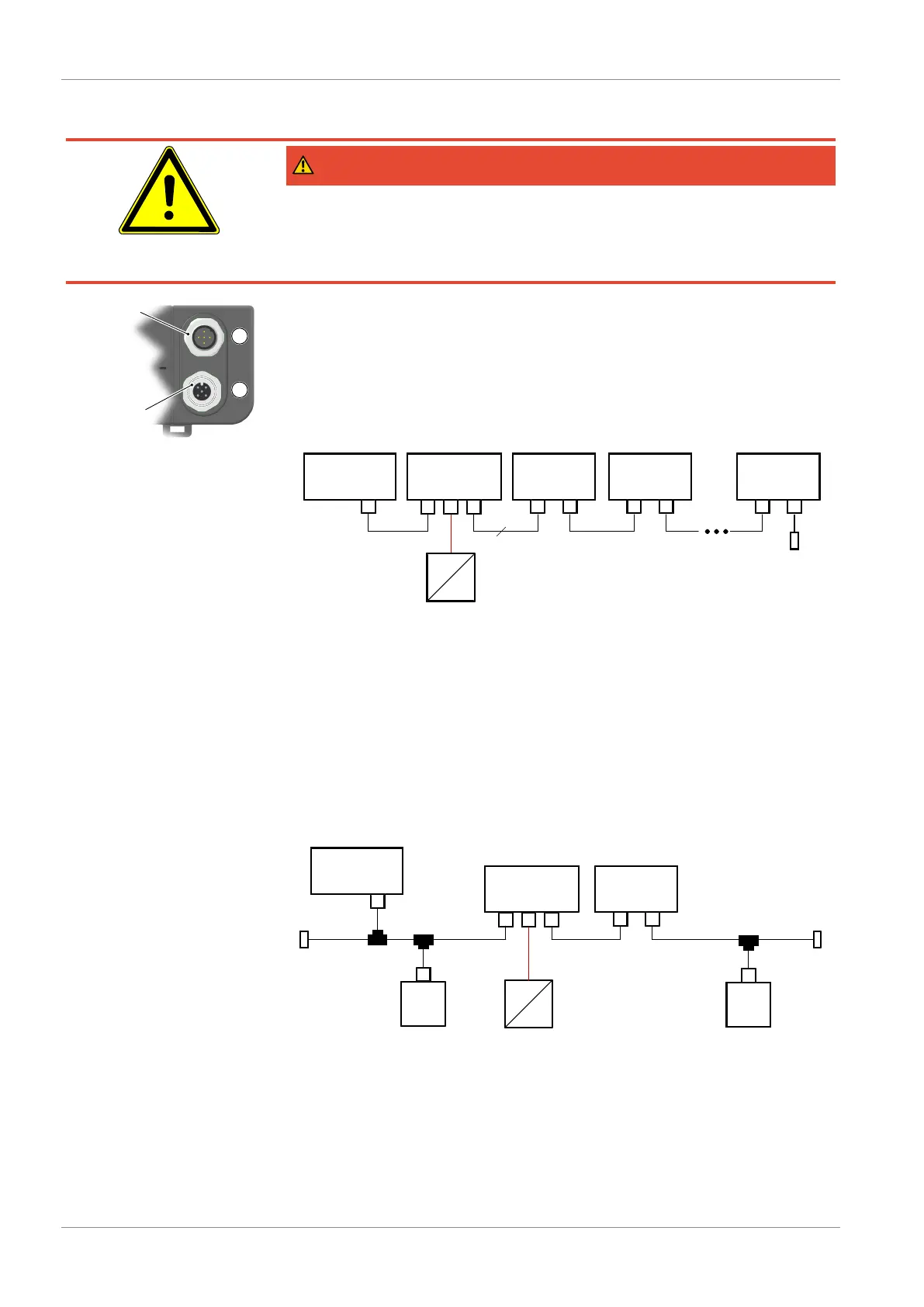
3.4.3 Device with Modbus
DANGER
Auxiliary for ATEX devices
When selecting the power supply, bear in mind that it may be a potential ignition
source.
Take suitable safety precautions to prevent this risk.
Fig.17: Replacement plate Mod-
bus
The devices with a Modbus interface do not have analog and switch outputs.
The replacement board is equipped with a 5-pin M12 flange connector for the
Modbus input and with a 5-pin M12 flange socket for the Modbus output.
The DE90 is usually connected to the Modbus RTU network as a so-called
slave to the Modbus RTU network. Up to 247 devices can be addressed in one
line network.
NOTICE!Star-shaped networks are not allowed.
MASTER DE90
1 2
DE90
1 2
DE90
1 2
Address 1 Address 2 Address 247
Bus termination
AC/DC
AC
M
Supply
1 2E
Modbus 5
Fig.18: Modbus RTU network
Communication is effected solely with the Modbus master. The connected
slaves only react to direct commands from the master, which is why communic-
ation between the slaves is not possible.
To guarantee fault-free data transmission, we recommend terminating the end
point of the Modbus RTU network with a 120 Ω resistor. This bus termination
resistance is available as an accessory.
3.4.3.1 Connection to an existing Modbus RTU network
It can be connected to an existing Modbus network via a conventional T-piece
(passive TAP).
MASTER
M
TAP
M
Slave
TAP
LT LT
M
Slave
TAP
DE90
1 2
Supply
1 2E
AC/DC
AC
Fig.19: Modbus connection